
LR3/Disco 3
force, restoring equilibrium with the diaphragm spring at its new location.
During the axial movement of the diaphragm spring, the adjuster ring takes up the increased distance between the spring
and cover. This ring contains raised segments, each having a ramp profile, which fits into a corresponding shape in the
clutch cover. When the diaphragm spring moves axially for wear compensation, three pre-loaded coil springs in the clutch
cover cause the adjuster ring to rotate, moving up the ramps and taking up the extra distance between the diaphragm
spring and clutch cover.
NOTE :
NOTE :
CLUTCH DRIVE PLATE
The clutch driven plate is of conventional design with a splined hub for locating the gearbox input spline. Lubricant is not
required on this interface. The friction material, which is lead and asbestos free, is connected to the hub by a spring pack,
which reduces torsional inputs into the transmission.
DUAL MASS FLYWHEEL
During operation, the adjuster ring rotates in a clockwise direction, as viewed from the transmission. If, for any
reason, a worn driven plate is replaced in service but the clutch cover assembly is to be reused, the adjuster ring
must be rotated back to its pre-loaded position. This operation requires the use of a press to release load on the
clutch whilst the adjuster ring is repositioned and is not recommended as a service action. However, It is
recommended that a complete clutch cover assembly and driven plate are used together in any service repair.
If, for any reason, the clutch cover and driven plate are removed and the driven plate is found to be capable of
further use, then the original cover/driven plate can be re-installed without the need for any adjustment.
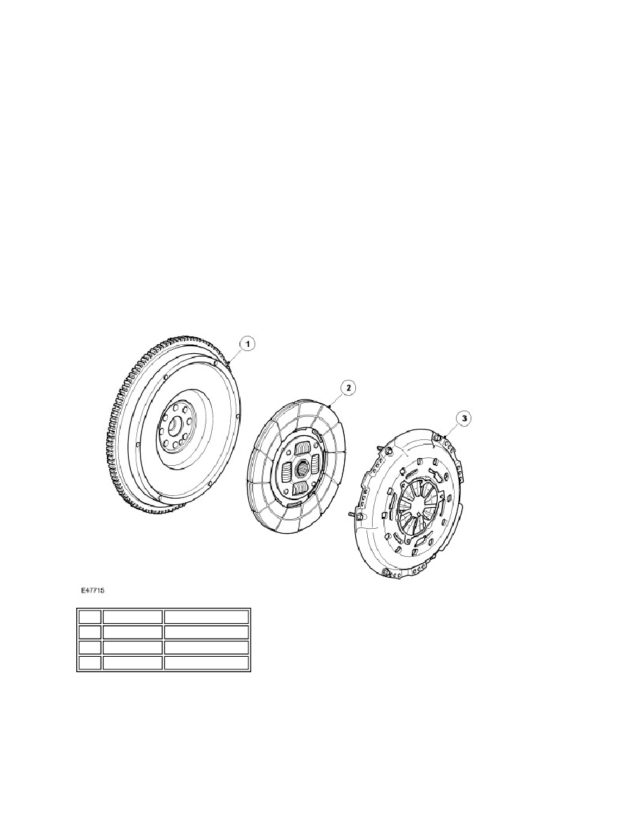
Item Part Number
Description
1
-
Dual mass flywheel
2
-
Drive plate
3
-
Pressure plate