
LR3/Disco 3
The rear casing assembly provides the location for the rear output flange bearing, the transfer box motor and the oil fill
and drain plug. Fins are cast into the rear casing assembly to improve the heat dissipation. The unit number is also
stamped into the rear housing.
OIL PUMP
An oil pump assembly is located in the front casing to provide lubrication for the bearings and rotary components through
cross-drillings in the input shaft. A flat-sectioned coupling on the input shaft drives the rotor of the pump; the stator is fixed
to the front housing assembly. A tube is attached to the pump, which leads into a calm suction area at the bottom of the
two casing assemblies. The collector magnet in the suction area of the pump collects any metallic debris.
CHAIN DRIVE
The chain-drive transfers drive from the centre differential to the front output flange. A 3/8" pitch chain connects the
sprocket on the transfer box input shaft with the sprocket on the front output flange. As both sprockets have the same
number of teeth, the rotational speed of both sprockets is identical.
TRANSFER BOX MOTOR
One motor operates both the high/low range change and the differential locking and torque-biasing device (multi-plate
clutch). The motor solenoid switches between the two functions, while the motor provides the rotational movement for
both operations.
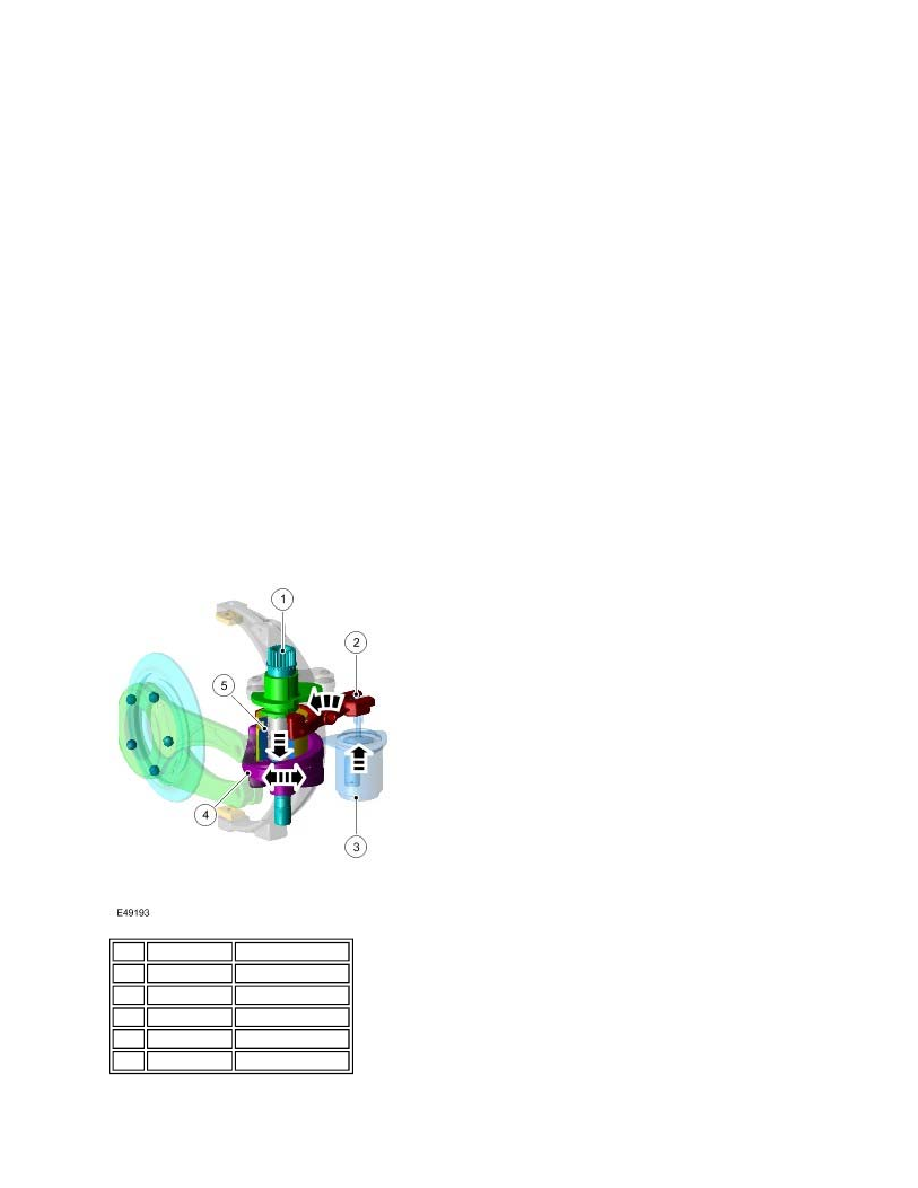
Transfer Box Motor Position For Clutch Control Mode
To actuate the multi-plate clutch, the transfer box control module energizes the solenoid (3). The solenoid pin pivots the
Item Part Number
Description
1
-
Motor shaft
2
-
Solenoid shift fork
3
-
Solenoid
4
-
Clutch control disc
5
-
Shifting sleeve