
LR3/Disco 3
solenoid shift fork (2), which engages the shifting sleeve (5) into the dogteeth on the clutch control disc (4). The rotational
movement of the motor shaft (1) is then linked to the clutch control disc via the shifting sleeve.
This is the normal operating mode of the transfer box. In this position, the range change function is disengaged and
mechanically locked.
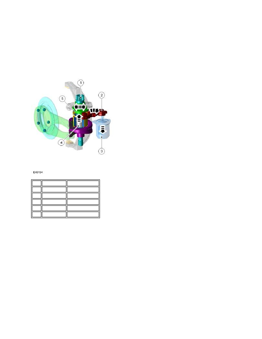
Transfer Box Motor Position For High/Low Range Mode
To actuate the high/low range change, the transfer box control module de-energizes the solenoid (3). A spring in the
solenoid retracts the solenoid pin and rotates the solenoid shift fork (2). This engages the shifting sleeve (4) to the
dogteeth on the high/low actuation cam (5). The rotational movement of the motor shaft (1) is then linked to the cam.
In this position, the multi-plate clutch is open, the differential cannot be locked and torque cannot be biased. Once the
range change is complete the system returns to clutch control mode. In the event of an electrical failure, the motor will
default to this position.
CENTRE DIFFERENTIAL ASSEMBLY
Item Part Number
Description
1
-
Motor shaft
2
-
Solenoid shift fork
3
-
Solenoid
4
-
Shifting sleeve
5
-
Actuation cam