
LR3/Disco 3
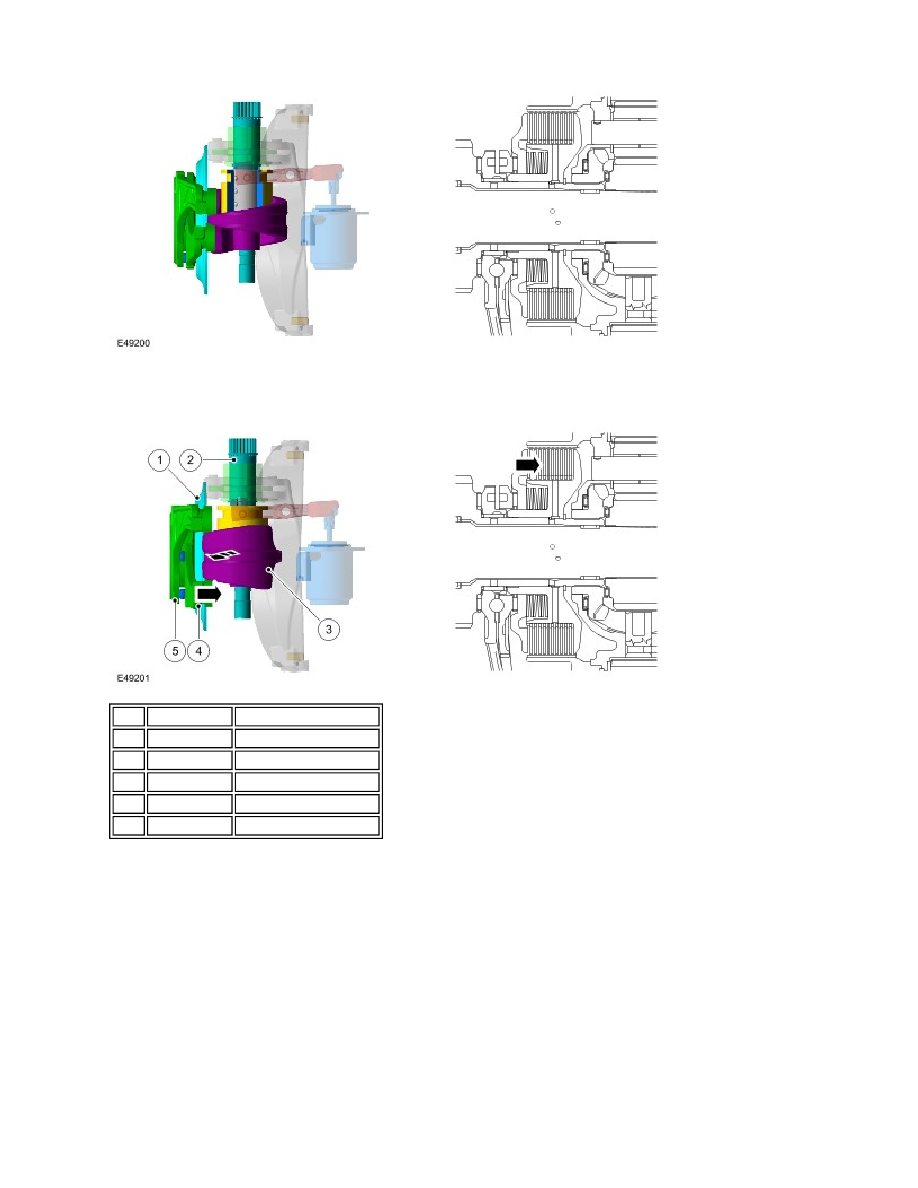
Transfer box motor in end position, multi-plate clutch closed condition
By turning the clutch control disc (3), via the motor shaft (2), the motor levers (4) are rotated relative to each other. This
relative movement acts on 5 balls (5) in a ramp mechanism between the two levers and give a defined axial movement.
The movement forces the clutch piston (1) to induce friction between the plates supported by the clutch hub and the
plates supported by the clutch basket on the differential carrier. This frictional force inhibits the differential rotation; the
differential carrier and front differential side gear are locked together.
TRANSFER BOX CONTROL MODULE
The transfer box control module controls the high/low 'shift-on-the-move' actuation and the multi-plate clutch actuation.
The control module is located in the E-box, next to the Engine Control Module (ECM), behind the battery in the engine
compartment. The position of the control module changes with LH and RH drive vehicles.
Item Part Number
Description
1
-
Clutch piston
2
-
Motor shaft
3
-
Clutch control disc
4
-
Motor levers
5
-
Ramp mechanism balls