
LR3/Disco 3
The control module is connected to the Controller Area Network (CAN) bus and controls the transfer box operation using
CAN messages from other control modules on the network.
The control module memorises the position of the transfer box motor when the ignition is switched off.
The transfer box control module uses the same actuator to control both range change function and application of centre
differential locking torque. The module uses position feed back from the actuator to provide smooth range changing
capability and graduated application of locking torque appropriate for the current driving conditions. Range change can be
carried out while moving providing the transmission is in neutral and the vehicle is below the speed necessary for the
requested range change.
The control module uses three connectors for all inputs and outputs. It receives a permanent power supply via a 30A
fusible link located in the Battery Junction Box (BJB), and an ignition supply via fuse 24 in the Central Junction Box (CJB).
The control module uses a series of programmed shift maps to control the synchronisation speed and ensure that a
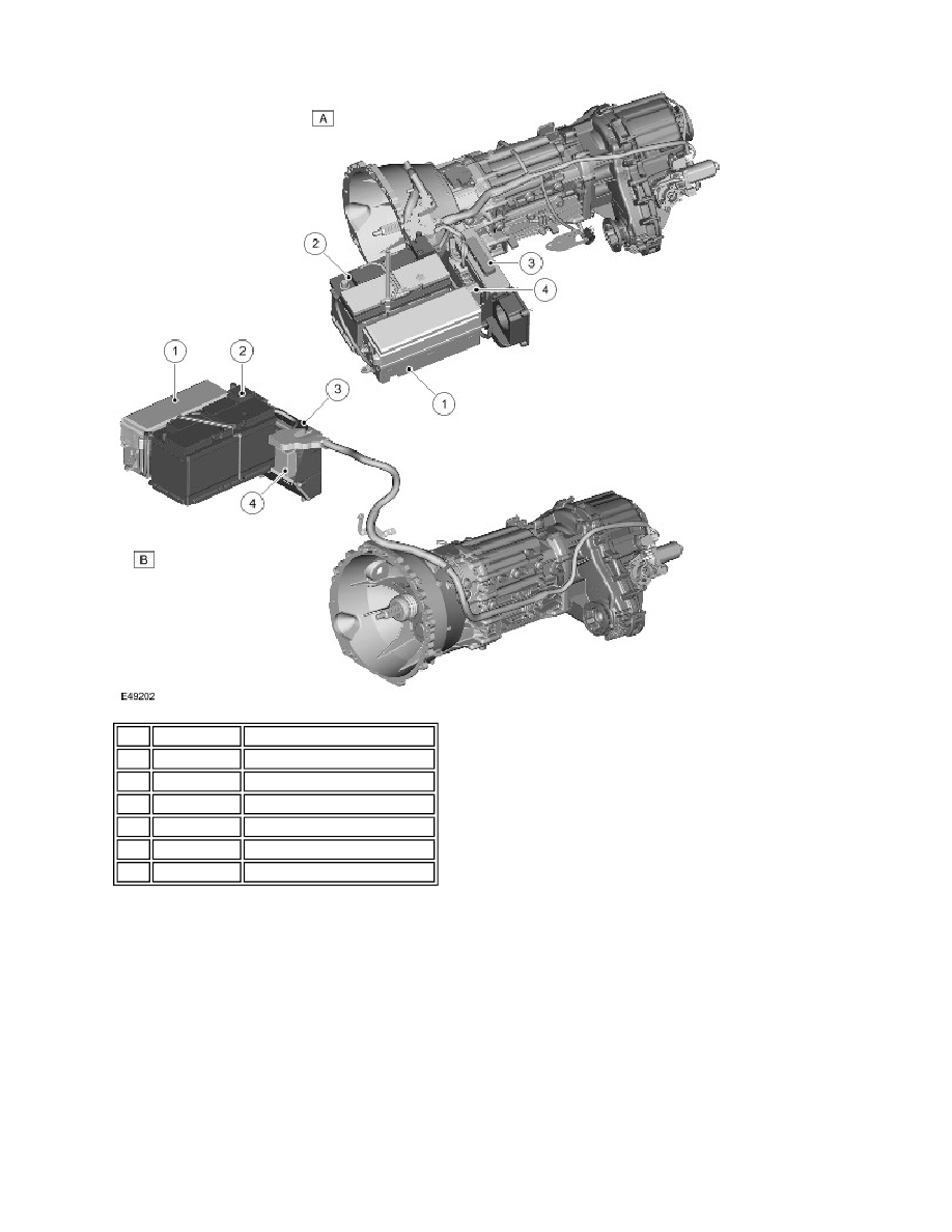
Item Part Number
Description
A
-
RH drive
B
-
LH drive
1
-
Battery Junction Box (BJB)
2
-
Battery
3
-
Engine Control Module (ECM)
4
-
Transfer box control module