
LR3/Disco 3
The solenoid coil of the auxiliary fuel pump is installed around a housing which contains a plunger and piston. The piston
locates in a bush, and a spring is installed on the piston between the bush and the plunger. A filter insert and a fuel line
connector are installed in the inlet end of the housing. A non return valve and a fuel line connector are installed in the fuel
outlet end of the housing.
While the solenoid coil is de-energized, the spring holds the piston and plunger in the closed position at the inlet end of
the housing. An O-ring seal on the plunger provides a fuel tight seal between the plunger and the filter insert, preventing
any flow through the pump. When the solenoid coil is energized, the piston and plunger move towards the outlet end of
the housing, until the plunger contacts the bush; fuel is then drawn in through the inlet connection and filter. The initial
movement of the piston also closes transverse drillings in the bush and isolates the pumping chamber at the outlet end of
the housing. Subsequent movement of the piston then forces fuel from the pumping chamber through the non return valve
and into the line to the FFBH. When the solenoid de-energizes, the spring moves the piston and plunger back towards the
closed position. As the piston and plunger move towards the closed position, fuel flows past the plunger and through the
annular gaps and transverse holes in the bush to replenish the pumping chamber.
SYSTEM OPERATION
The FFBH system supplements vehicle heater performance while the engine is running, and is transparent to the driver.
Operation of the FFBH is controlled by a medium speed CAN bus message from the ATCM, which contains the operating
mode required of the FFBH. When the message contains the heating mode, the control module in the FFBH starts the
FFBH.
While the medium speed CAN bus is active, the control module sends these messages:
The control module will not start the FFBH, or will discontinue operation, if any of the following occur:
The control module is in the lockout mode (see Diagnostics at the end of this section).
A crash message is received from the restraints control module. For additional information, refer to
Air Bag and
Safety Belt Pretensioner Supplemental Restraint System (SRS)
(501-20B Supplemental Restraint System)
A low fuel level message is received from the instrument cluster. For additional information, refer to
Instrument
Cluster
(413-01 Instrument Cluster)
The battery voltage is too low. When starting the FFBH, battery voltage must be 10.25 - 15.5 volts. When the
FFBH is running, operation will be discontinued if battery voltage decreases to less than 10.25 volts.
The FFBH is controlled at one of two heat output levels, 2.5 kW at part load combustion and 5 kW at full load combustion.
Start Sequence: At the beginning of a start sequence, the control module energizes the glow pin function of the glow pin
and flame sensor, to pre heat the combustion chamber, starts the combustion air fan at slow speed and energizes the
coolant circulation pump. After approximately 30 seconds, the control module energizes the auxiliary fuel pump at the
starting sequence speed. The fuel delivered by the auxiliary fuel pump evaporates in the combustion chamber, mixes with
air from the combustion air fan and is ignited by the glow pin and flame sensor. The control module then progressively
increases the speed of the auxiliary fuel pump and the combustion air fan. Once combustion is established the control
module switches the glow pin and flame sensor from the glow pin function to the flame sensing function to monitor
combustion. From the beginning of the start sequence to stable combustion at full load takes approximately 150 seconds.
Coolant Temperature Control: While the FFBH is running, the control module cycles the FFBH between full load
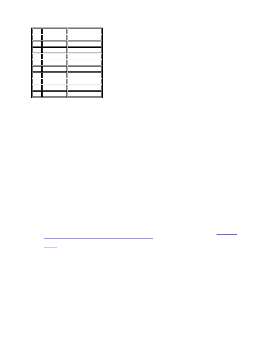
Item Part Number
Description
1
-
Fuel line connector
2
-
Non return valve
3
-
Solenoid coil
4
-
Plunger
5
-
Filter insert
6
-
Fuel line connector
7
-
O-ring seal
8
-
Spring
9
-
Piston
10
-
Bush