
LR3/Disco 3
combustion, part load combustion and a control idle phase of operation, depending on the temperature of the coolant in
the heat exchanger. The parked heating and auxiliary heating modes use different switching point temperatures from the
supplementary heating mode, as detailed below.
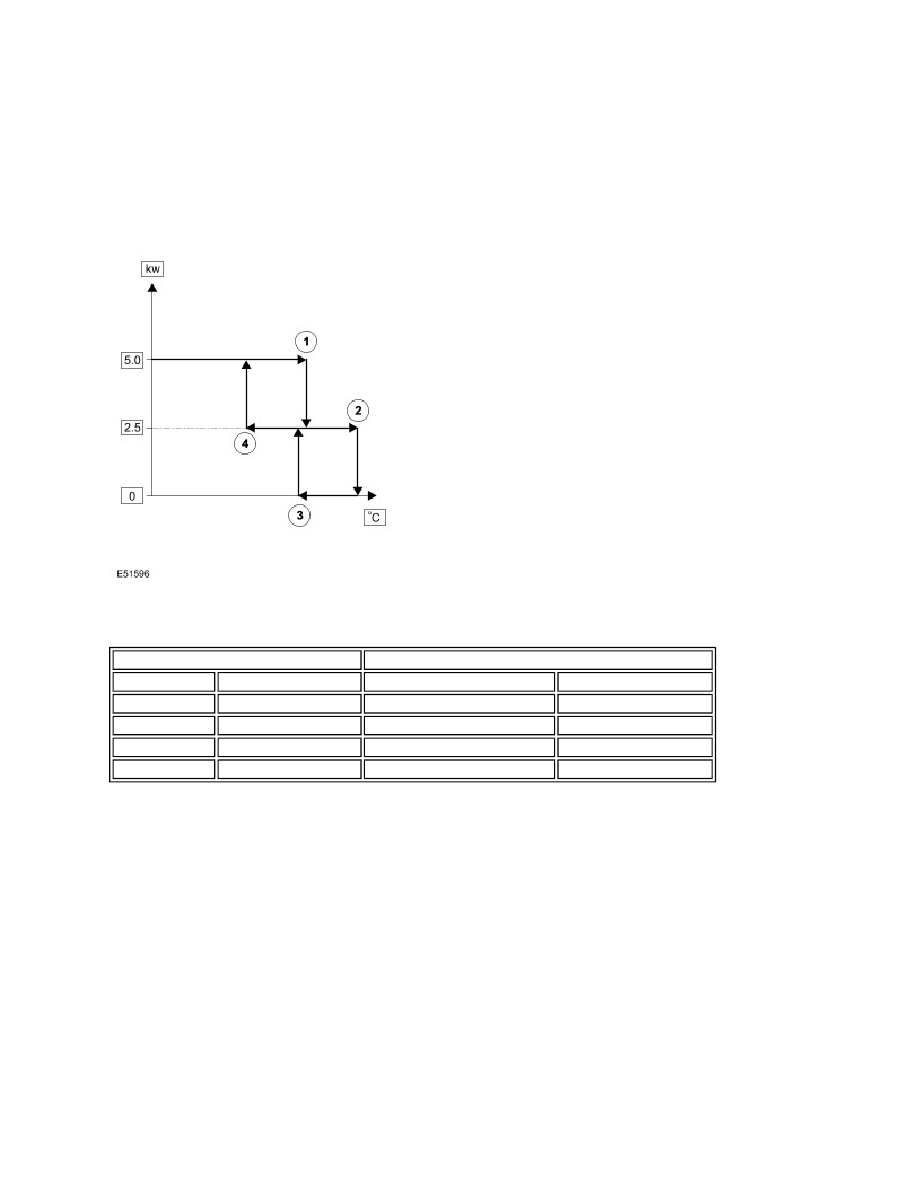
Switching Point Diagram
Switching Point Temperatures
After the start sequence, the control module maintains full load combustion until the coolant temperature reaches
switching point temperature 1. At this temperature, the control module decreases the speed of the auxiliary fuel pump and
the combustion air fan to half speed, to produce part load combustion. The control module maintains part load
combustion while the coolant temperature remains between switching point temperatures 2 and 4. At part load
combustion the temperature of the coolant will increase or decrease depending on the amount of heat required to heat
the vehicle interior. If the coolant temperature decreases to switching point temperature 4, the control module increases
the speed of the auxiliary fuel pump and the combustion air fan to full speed, to return to full load combustion. If the
coolant temperature increases to switching point temperature 2, the control module enters a control idle phase of
operation.
On entering the control idle phase, the control module immediately switches the auxiliary fuel pump off, to stop
combustion, and starts a timer for the combustion air fan. After a 2 minute cool down period, the control module switches
the combustion air fan off and then remains in the control idle phase while the coolant temperature remains above
switching point temperature 3. If the coolant temperature decreases to switching point temperature 3, the control module
initiates a start to part load combustion. A start to part load combustion takes approximately 90 seconds.
In order to limit the build up of carbon deposits on the glow pin and flame sensor, the control module also enters the
control idle phase if continuous combustion time exceeds 72 minutes (at part load, full load or a combination of both).
After the cool down period, if the coolant is still in the temperature range that requires additional heat, the control module
restarts the FFBH.
Switching Point
Temperature, °C (°F)
Figure Item No.
Description
Parked and Auxiliary Heating Supplementary Heating
1
Full load to part load
76 (169)
72 (162)
2
Part load to control idle
82 (180)
78 (172)
3
Control idle to part load
74 (165)
70 (158)
4
Part load to full load
69 (156)
65 (149)