
LR3/Disco 3
Trip computer functions. For additional information, refer to
Information and Message Center
(413-08 )
The high beam on and flash functions are connected on separate wires to the CJB. When the switch is operated in either
position an earth path is completed which is sensed by the CJB which activates the selected function.
The turn signal lamps are connected and operate in a similar way with the earth path completed through a separate wire
which is sensed by the CJB which activates the applicable turn signal lamps.
HAZARD FLASHERS
The hazard flashers are controlled by a non-latching switch in the centre of the instrument panel. The hazard flashers
operate at all times when selected and are not dependant on ignition switch position.
When the hazard flashers are selected on, all of the front, rear and side turn signal lamps operate as previously described
and both left and right turn signal indicators in the instrument cluster also flash. The hazard warning flashers flash at a
rate of 380ms on and 380ms off. When the hazard flashers are active, they override any request for turn signal lamp
operation.
If a trailer is fitted, the trailer turn signal lamps will flash at the same frequency as the vehicle indicators. The trailer
warning indicator in the instrument cluster will also flash. If a trailer bulb is defective, the trailer warning indicator will not
flash.
The hazard flashers can also be activated by a crash signal from the restraints control module. This is received by the
CJB which activates the hazard flashers. The hazard flashers can be cancelled by moving the ignition switch to the
auxiliary position I or the off position O or the crash mode is cancelled by the restraints control module. For additional
information, refer to
Air Bag and Safety Belt Pretensioner Supplemental Restraint System (SRS)
(501-20B )
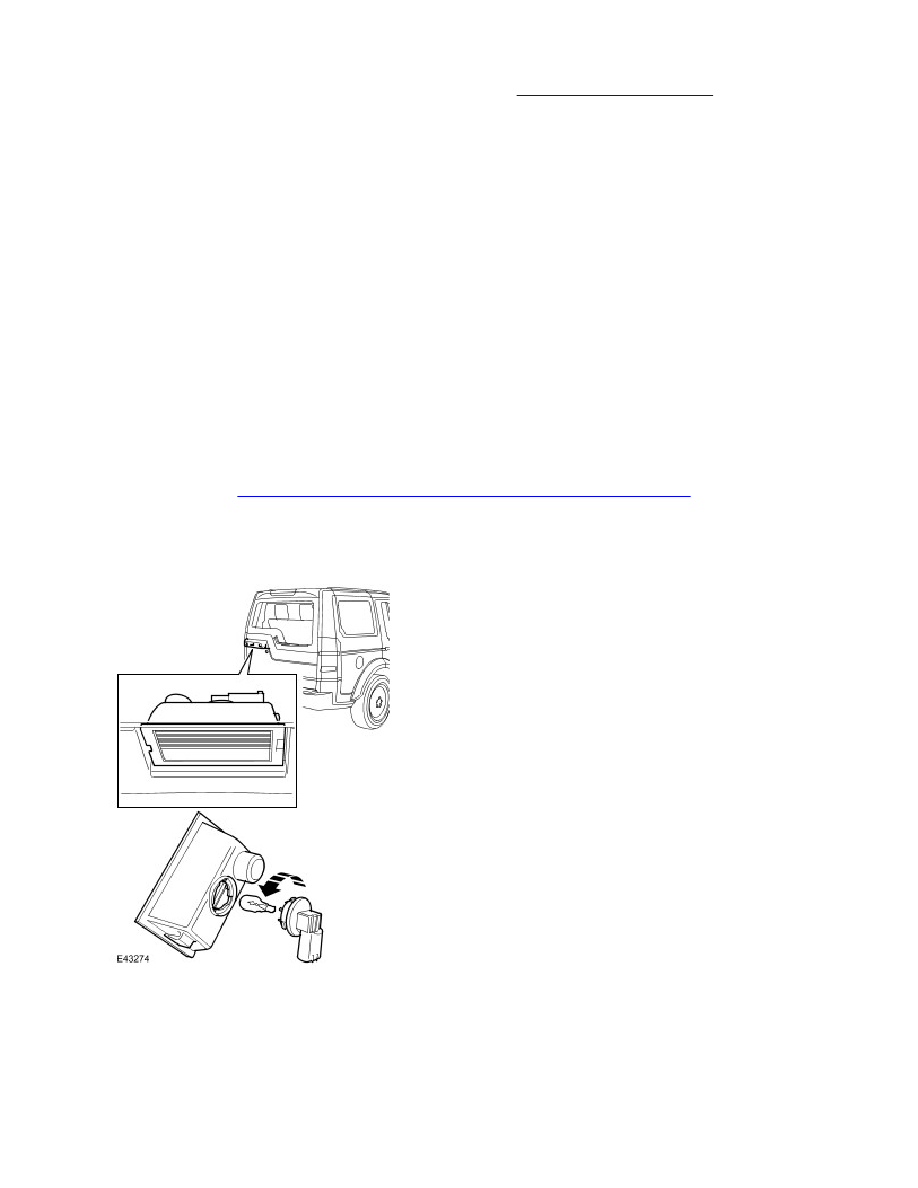
LICENSE PLATE LAMPS
Two license plate lamps are fitted in the tailgate handle, above the license plate in the upper tailgate. Each lamp uses a
5W capless type bulb. The lamps are secured in the upper tail gate handle with integral clips. The lamps can be released
from the handle using a small, flat blade screwdriver.
The license plate lamps are active at all times when the side lamps or headlamps are switched on.
HIGH MOUNTED STOP LAMP