
LR3/Disco 3
specific to Japan market and the part number is different. The system also has extra components for the VICS system (a
receiver and an antenna). The VICS system receives allows the vehicle to receive information about traffic conditions
from roadside transmitters and adjust the navigation instructions accordingly. The VICS information is received by both a
radio link and an infra red link. For this reason the antenna is located on the inside of the windscreen.
The navigation computer is connected to the TSD by a private CAN bus and a dedicated GVIF (Gigabit Video Interface).
The GVIF carries all the video information to the TSD, while the CAN bus is used for data and control instructions to and
from the TSD.
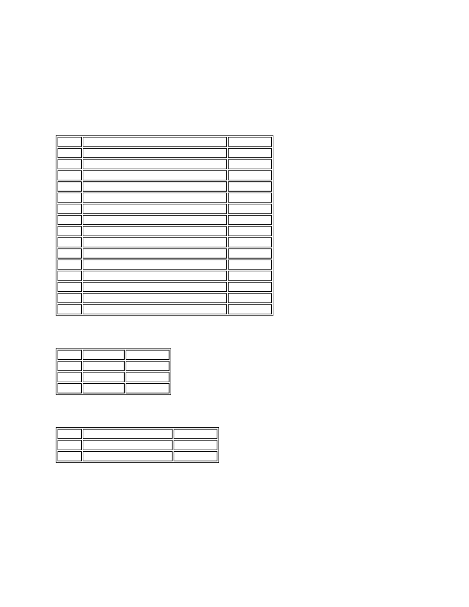
Connector No C2114 Pin Out Table
Connector No C2113 Pin Out Table
Connector No C1599 Pin Out Table
GPS Antenna
Pin No
Description
Input/Output
3
Ground
-
6
Private CAN Low
Input/Output
8
VICS receiver H-GND
Input
9
VICS reciever H-TX-
Input
14
Navigation and voice audio ground
-
15
Mic screen ground
-
16
Voice recognition microphone -
-
17
12V Battery voltage (fuse 49)
Input
18
12V Battery supply from infotainment relay
Input
19
Ground
-
21
Vehicle speed signal from ABS control module
Input
22
Private CAN high
Input/Output
30
Navigation and voice audio +
Output
31
Navigation and voice audio screen/ground
-
32
Voice recognition microphone +
Input
Pin No Description Input/Output
1
GVIF +
Output
2
GVIF -
-
3
GVIF ground
-
Pin No
Description
Input/Output
1
GPS antenna screen ground Output
2
GPS antenna signal
Input