
LR3/Disco 3
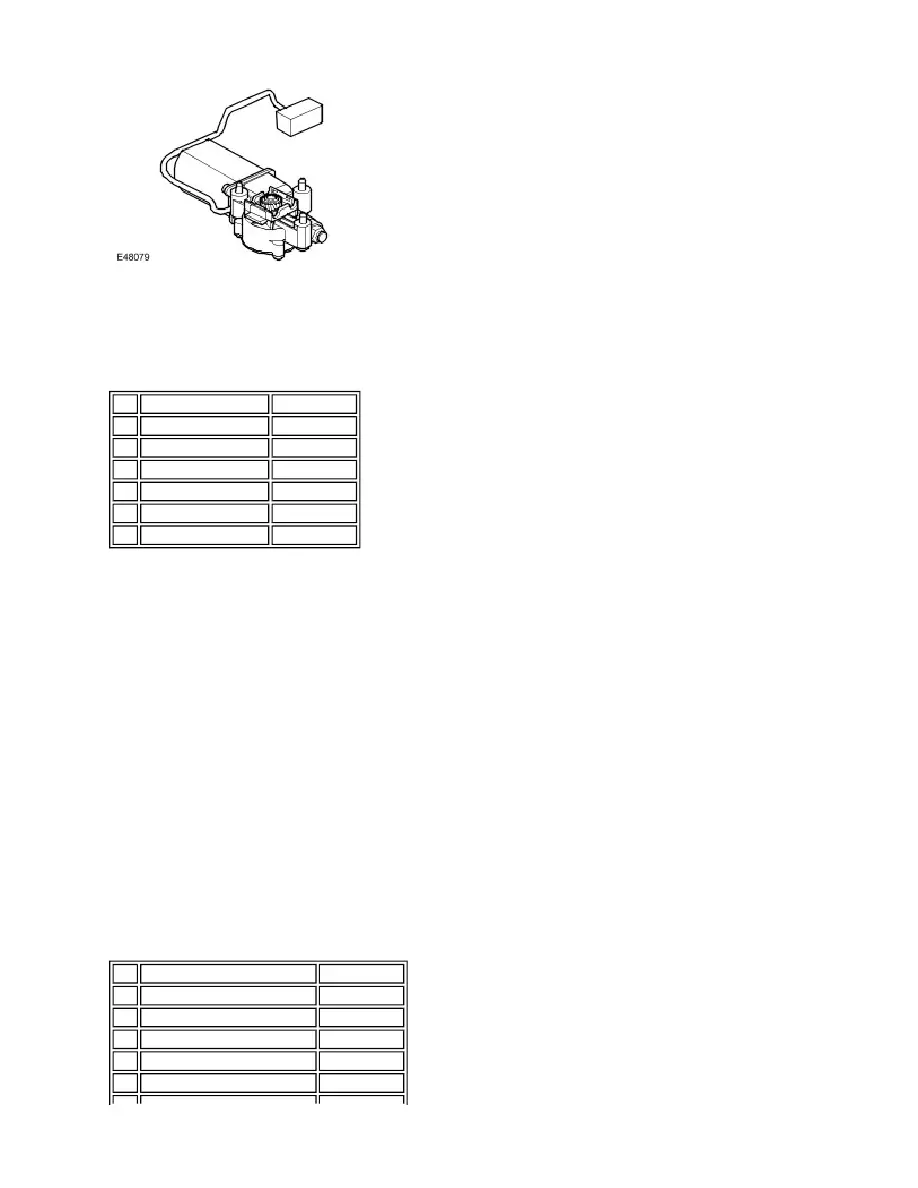
The sunroof motor has a worm drive, which drives a gear in a cast housing attached to the end of the motor. The gear
has a small pinion gear attached to the outer part of its spindle. The pinion engages with the helixed cables to form a rack
and pinion drive. Rotation of the motor turns the pinion, which in turn drives the cables in the required direction.
Sunroof Motor Pin Out Information
The two cables are attached either side of the pinion. One end of each cable is attached to the guide. The opposite end is
trapped in its position on the pinion by a metal insert in the frame. The cables run in channels in the frame to the guides.
As the sunroof panel is closed, the cables are pushed through channels in the rear of the frame. The displaced cable is
guided into a further two channels in the frame, which protect the cable and prevent the cable snagging creating noise.
The cables are made from rigid spring steel and therefore can pull as well as push the sunroof along the guides.
A sun blind is also located in the guides integrated into the frame. The sunblind is operated manually, independently of
the glass panels position. To move to the closed position the sunblind handle is pushed forward until it latches into the
frame. To move the sunblind to the open position the sunblind handle is pushed up, to unlatch and either released or
retracted to the open position. The sunblind can only be in either the fully open or fully closed positions.
Drain hoses are connected to the front and rear corners of the frame. The drain hoses are located inside of the cabin on
the ’A’ and ’C’ post pillars to allow water, which has collected in the frame to escape. A one-way valve is fitted to the end
of each drain hose to prevent the ingress of dirt and moisture.
SUNROOF CONTROL MODULE
The sunroof control module is mounted on the rear of the frame, and is connected to the motor at one end as described
above, and to the vehicle electrical system at the other. It takes the inputs from the vehicle, such as LIN (Local
Interconnect Network) bus signals and switch signals, and controls motor movement appropriately. It also contains the
algorithm for the anti-trap system.
Sunroof Control Module Pin Out Information
Pin
Description
Input/Output
1
Hall sensor Ground
-
2
Hall sensor Supply
Input
3
Hall sensor Speed
Output
4 Hall sensor Direction
Output
5
Motor A
Input
6
Motor B
Input
Pin
Description
Input/Output
1
Switch Ground
-
2
Switch Open
Input
3
Switch Close
Input
4
Not used
-
5
Not used
-