
LR3/Disco 3
The clockspring is installed on the steering column to provide the electrical interface between the fixed wiring harness of
the steering column and the components that rotate with the steering wheel, i.e. the driver air bag, the horn and the
steering wheel switch packs.
The clockspring consists of a plastic cassette which incorporates an outer cover fixed to the steering column and an inner
rotor which turns with the steering wheel. Four securing lugs attach the cover to the multifunction switch on the steering
column. The rotor is keyed to the steering wheel by a drive peg. A lug on the underside of the rotor operates the self-
cancelling feature of the turn signal indicator switch. A ribbon lead, threaded on rollers in the rotor, links two connectors
on the cover to two connectors on the rotor. Link leads for the driver air bag are installed in one of the connectors on the
rotor.
To prevent damage to the ribbon lead, both the steering and the clockspring must be centralized when removing and
installing the clockspring or the steering wheel. The clockspring is centralized when the drive peg is at six o'clock and 50 -
100% of a yellow wheel is visible in the viewing window.
Replacement clocksprings are fitted with a stopper, which locks the cover to the rotor, in the central position. The stopper
must be broken off when the replacement clockspring is installed.
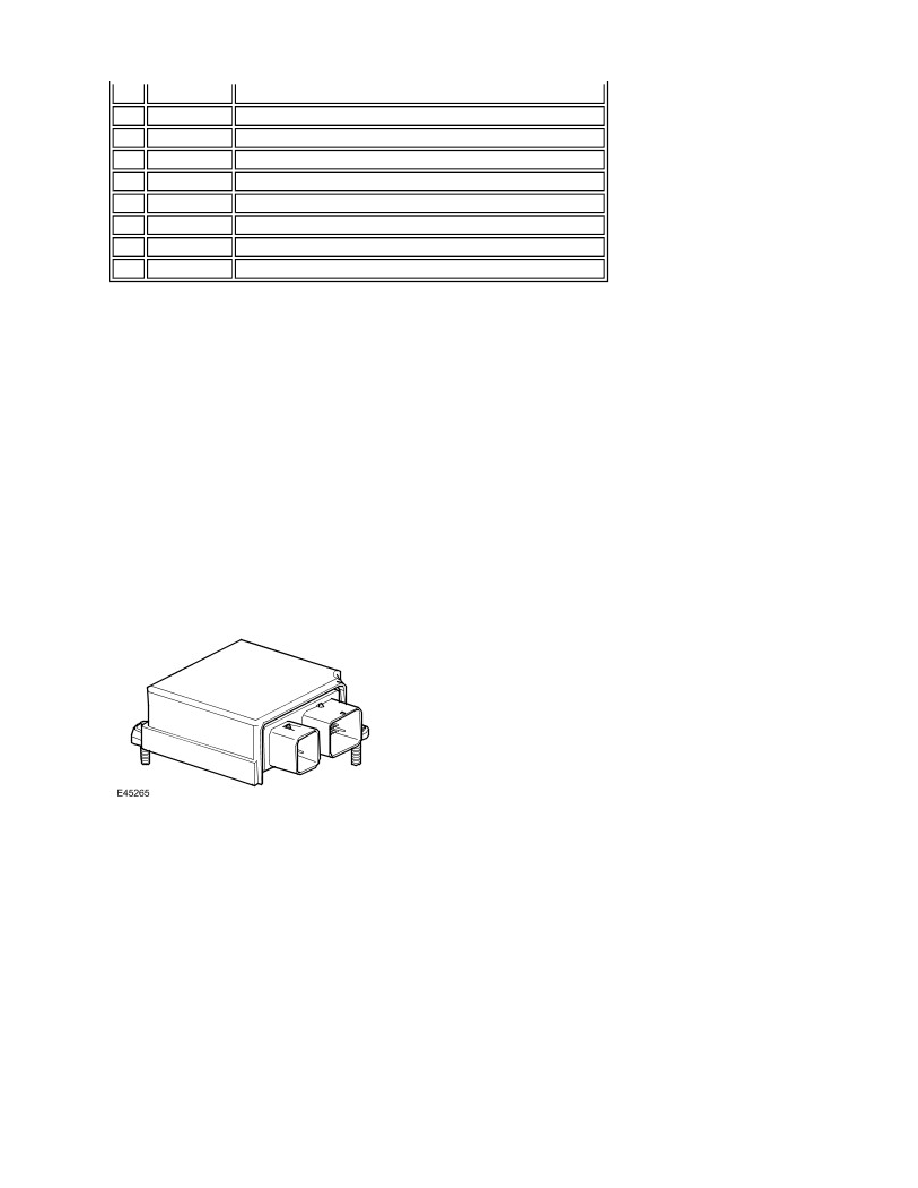
RCM (restraints control module)
The RCM (restraints control module) is installed on the top of the transmission tunnel, in line with the B pillars, and
controls operation of the SRS. The main functions of the RCM (restraints control module) include:
Crash detection and recording.
Air bag and pretensioner firing.
Self test and system monitoring, with status indication via the SRS (supplemental restraint system) warning lamp
and non volatile storage of fault information.
A safing sensor in the RCM (restraints control module) provides confirmation of an impact to verify if air bag and
pretensioner activation is necessary. A roll-over sensor monitors the lateral attitude of the vehicle. Various firing strategies
are employed by the RCM (restraints control module) to ensure that during an accident only the appropriate air bags and
pretensioners are fired. The firing strategy used also depends on the inputs from the safety belt switches and the
occupant monitoring system.
An energy reserve in the RCM (restraints control module) ensures there is always a minimum of 150 milliseconds of
stored energy available if the power supply from the ignition switch is disrupted during a crash. The stored energy is
sufficient to produce firing signals for the driver air bag, the passenger air bag and the safety belt pretensioners.
1
-
Electrical connector for steering wheel switch packs and horn
2
-
Inner rotor
3
-
Outer housing securing lug
4
-
Driver air bag link leads
5
Viewing window
6
-
Drive peg
7
-
Stopper
8
-
Electrical connector for steering column harness
9
-
Outer cover