
Heating and ventilation (with A/C) – circuit diagram
- Make
- Land Rover
- Model
- Range Rover P38 Electrical Troubleshooting Manual
- Year
- 1999 on
- Section
- Circuit diagram › Heating and ventilation (with A/C) – circuit diagram
‹ Prev Heating and ventilation (with A/C) – circuit diagram rev: 11/99Next › Heating and ventilation (with A/C) – circuit diagram
Heating and ventilation (WITH A/C)Heating and ventilation (with A/C) – circuit diagram
HEATING AND VENTILATION (WITH A/C) – CIRCUIT DIAGRAM
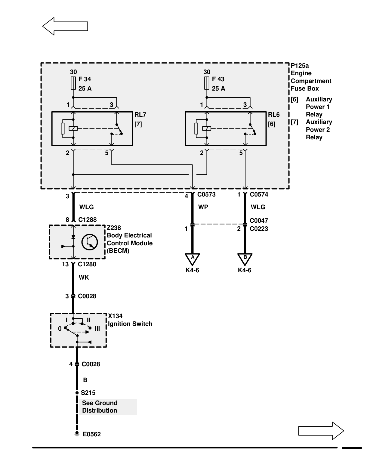
Components on this page
- X134 Ignition Switch
- Z238 Body Electrical Control Module (BECM)
‹ Prev Heating and ventilation (with A/C) – circuit diagram rev: 11/99Next › Heating and ventilation (with A/C) – circuit diagram
Parts & tools for this job For 1999 Land Rover Range Rover
- TOOLA/C manifold gauge setSearch: AC manifold gauge set
- TOOLUV leak detection kitSearch: AC UV leak detection kit
- PARTCabin filterSearch: Land Rover Range Rover 1999 cabin filter
Links open Amazon search results in a new tab. As an Amazon Associate I earn from qualifying purchases.