
Range Rover P38
12
ENGINE
NEW RANGE ROVER
4
DESCRIPTION AND OPERATION
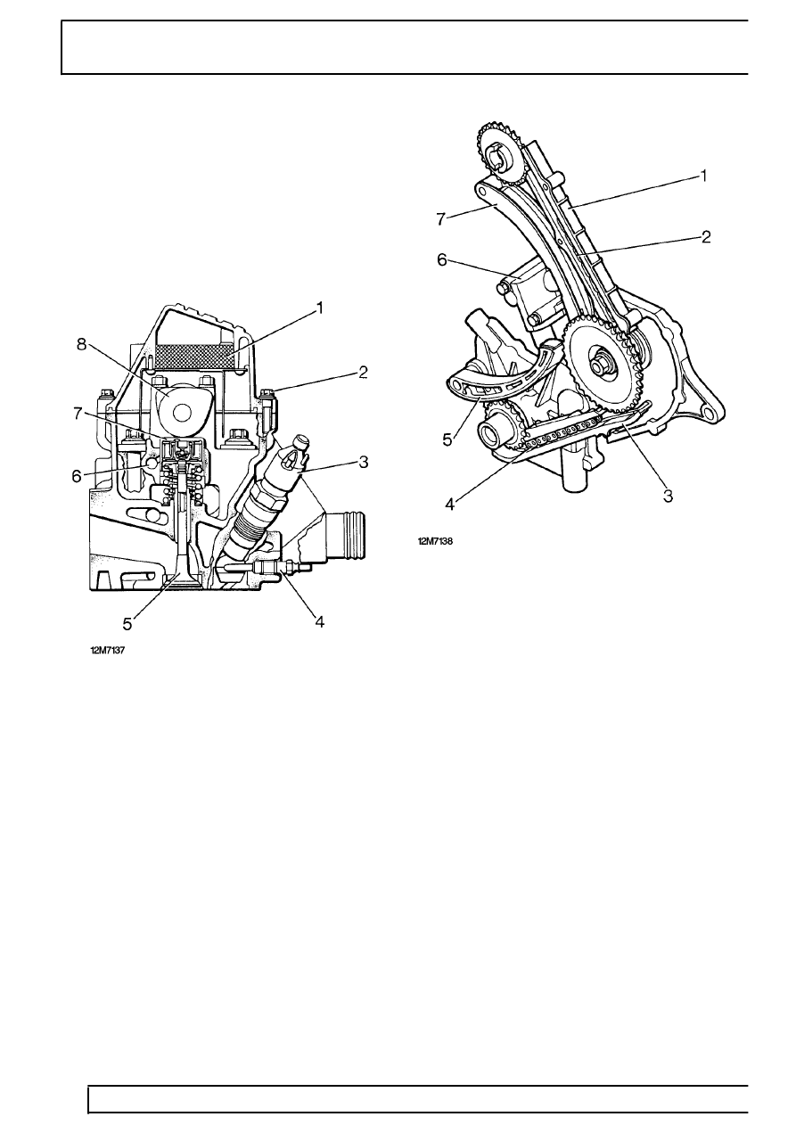
Cylinder head
The aluminium cylinder head houses the chain driven
overhead camshaft, the valve gear and fuel injectors.
Coolant enters the cylinder head from the crankcase.
The coolant flow is across the cylinder head and out
to the heater matrix and radiator.
An oil separator with wire mesh filter is installed in the
camshaft cover.
1. Oil separator
2. Camshaft cover bolts
3. Fuel injector
4. Glow plug
5. Outlet valve
6. Oil supply duct
7. Hydraulic tappet
8. Camshaft
Camshaft
Seven bearings support the camshaft in the cylinder
head. The camshaft is chain driven from the fuel
injection pump drive sprocket, which itself is chain
driven from the crankshaft. Both the injection pump
timing chain and the camshaft timing chain run within
guide rails and are tensioned automatically by tension
rails and a chain adjuster mechanism.
1. Guide rail
2. Camshaft drive chain
3. Guide rail
4. Injection pump drive chain
5. Tension rail
6. Chain adjuster
7. Tension rail
Valve gear
The camshaft operates the inlet and exhaust valves
through bucket-type tappets with hydraulic valve
clearance adjustment. The hydraulic tappets are
leakproof, eliminating rattle during the first few
revolutions of the engine. Valves are available in
standard size or oversize and are identified by a
number stamped on the stem. Valves are coated
during manufacture and DO NOT need to be lapped
when they are renewed.