
Range Rover P38
BMW DIESEL
51
REPAIR
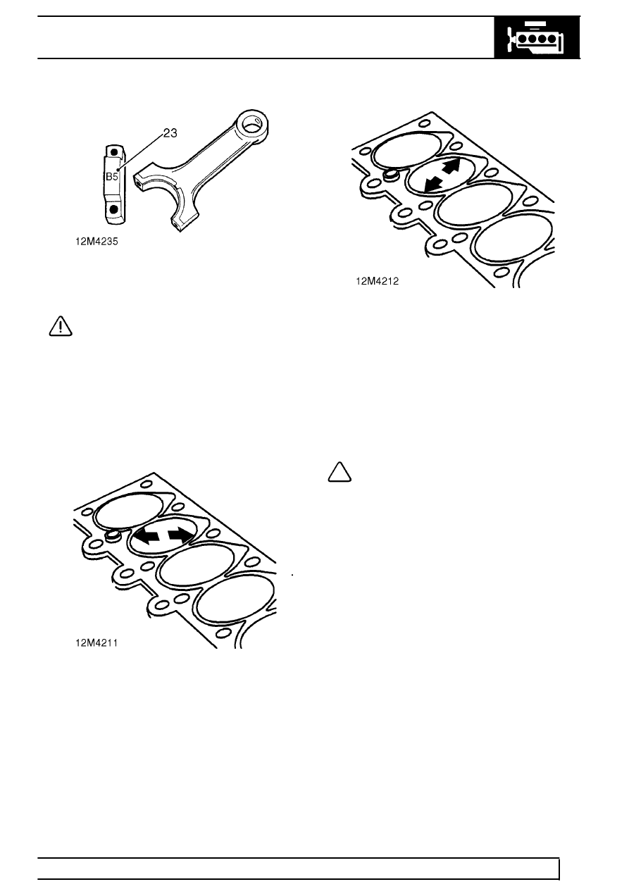
23. Replace connecting rods as necessary, do not
attempt to straighten distorted rods.
CAUTION: replacement connecting rods
must be of the same weight classification,
the classification is embossed on the main
bearing caps.
Cylinder bores - inspection
24. De-glaze cylinder bores, check bores for scoring.
25. Remove all traces of cylinder head gasket and
carbon deposits from cylinder block.
26. Check and record cylinder bore diameter at
bottom, centre and top of bore ensuring that
measurements are taken at the angle shown.
27. Compare figures obtained with the following and
determine cylinder bore size:
Standard = 80.00 to 80.04 mm (3.150 to 3.151
in)
Intermediate = 80.08 to 80.12 mm (3.153 to
3.154 in)
1st oversize = 80.25 to 80.29 mm (3.20 to 3.21
in)
28. Repeat procedure at angle shown and from the
2 sets of measurements obtained, calculate
cylinder bore ovality and taper:
Maximum ovality = 0.04 mm (0.002 in)
Maximum taper = 0.04 mm (0.002 in)
29. Compare piston diameter with cylinder bore size
and determine piston to bore clearance:
Piston to bore clearance = 0.031 to 0.063 mm
(0.0012 to 0.002 in)
NOTE: For engines which have been ’run
in,’ the above clearance may be increased
to 0.213 mm (0.008 in).
30. Standard and intermediate size cylinder bores
which are worn in excess of limits given may be
rebored to next oversize and the appropriate
oversize pistons fitted.