
Range Rover P38
LAND ROVER V8
49
DESCRIPTION AND OPERATION
Ignition coils
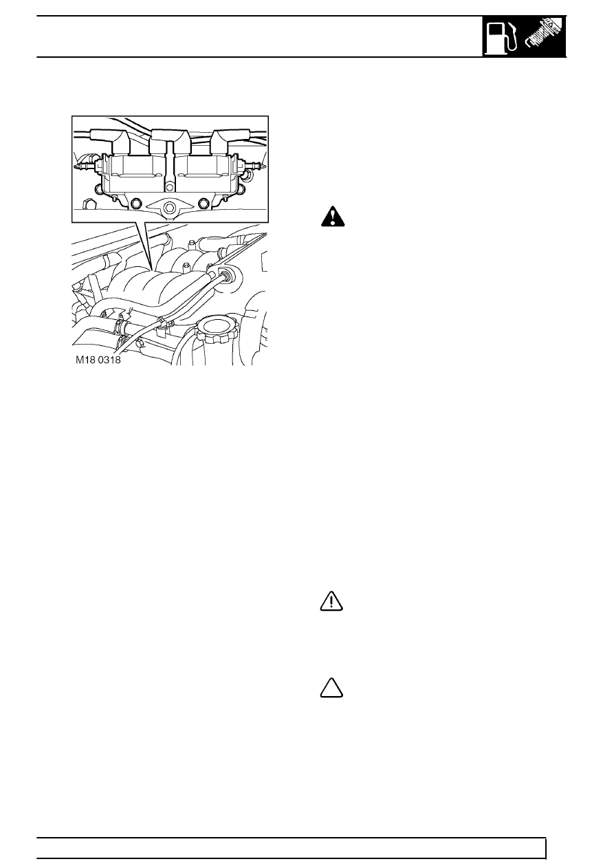
The electronic ignition system is fitted with two quad
coils which are directly driven by the ECM. The
ignition coils are mounted on a bracket fitted to the
rear of the engine. The circuit to each coil is
completed by switching within the ECM, allowing each
coil to charge. When the ECM determines the correct
ignition point, it switches off current supply to the coil
which in turn causes the magnetic field around the
coil’s primary winding to collapse, inducing ht voltage
in the secondary winding and in the iron core of the
coil. High tension voltage, of different polarities, is
produced at either end of the coil’s core and is
transmitted to two cylinders simultaneously, one on
compression stroke, the other on exhaust stroke. This
is called the wasted spark principle.
Note that coil 1 feeds cylinders 1 and 6, coil 2 feeds
cylinders 5 and 8, coil 3 feeds cylinders 4 and 7, and
coil 4 feeds cylinders 2 and 3. The resistance of the
spark plug in the compression cylinder is higher than
that in the exhaust cylinder and hence more spark
energy is dissipated in the compression cylinder. Coil
failure will result in a lack of ignition, resulting in a
misfire in the related cylinders. The fault is indicated
by illumination of the malfunction indicator light (MIL)
on North American specification vehicles.
The positive supply to the coils is fed via a common
fuse and ignition relay located in the engine
compartment fusebox. Each coil supply feed has an
RFI suppression capacitor fitted adjacent to the coil
mounting bracket. The ignition primary wires are
screened to suppress the emission of radio frequency
interference, with the screens being grounded at a
connection on the ECM.
WARNING: The ignition coils operate at
very high voltages, do not attempt repair
operations and procedures on the ignition
high tension / secondary system when the engine
is running.
The ECM calculates the dwell timing from battery
voltage and engine speed data to ensure sufficient
secondary (spark) energy is always available without
excessive primary current flow, thus avoiding
overheating or damage to the ignition coils.
The spark timing for each individual cylinder is
calculated by the ECM using an internal memory map
under consideration of the following inputs:
•
Engine speed
•
Engine load
•
Engine temperature
•
Knock control
•
Automatic gearbox shift control
•
Idle speed control
The nominal value for a warm engine at idle is
12
°
BTDC
CAUTION: Avoid running the engine if
there is a possibility of the secondary (ht)
becoming open circuit. This condition
could damage the ignition power stages and / or
the ignition coils through excessive energy being
reflected back into the primary circuit.
NOTE: Testbook is not able to perform
diagnostics to the primary power stage
coils. Ignition related faults are monitored
indirectly via the misfire detection system and its
fault codes (NAS vehicles only).