
19 - FUEL SYSTEM - LAND ROVER V8: DESCRIPTION AND OPERATION (page 22 of 32)
- Make
- Land Rover
- Model
- Range Rover P38
19
FUEL SYSTEM
NEW RANGE ROVER
52
DESCRIPTION AND OPERATION
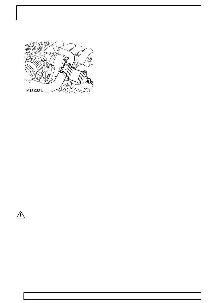
Idle Air Control Valve (IACV) - from 99MY
The idle air control valve is positioned at the top rear
of the engine, on the side of the air inlet pipe. The unit
is clamped to the inlet manifold by two bolts passing
through ’P’ clips.
A grey three-pin connector is provided at the back of
the unit. One wire supplies the voltage feed from the
engine compartment fusebox, while the other two
wires carry the valve positioning control signals.
The IACV is used to make adjustments to optimise the
engine idle speed under all operating conditions.
Engine load at idle will vary in reaction to a
combination of conditions and influences such as
engine friction, water pump , air conditioning, altitude
etc. The IACV utilises closed loop control to
compensate for the changing conditions by regulating
the air flow into the engine.
The IACV utilises two electromagnetic coils which use
opposing PWM signals to control the positioning of a
rotary valve. The rotary valve position determines how
much air is allowed to flow through the bypass route.
CAUTION: Do not try to forcibly set the
valve position, the actuator cannot be
serviced. In the event of failure the IACV
must be replaced as a unit.
If one of the electrical circuits supplying the PWM
signals fails, the ECM switches off the other circuit to
prevent the valve from biasing towards a maximum or
minimum setting. Under these conditions, a default
position for the valve is provided by a permanent
magnet, which sets the valve position to maintain the
idle speed at a fixed value of approximately 1200 rpm
with no load applied.
During cold start conditions, the idle speed is held at
1200 rpm in neutral for 20 seconds. Ignition timing is
retarded as a catalyst heating strategy.
If the IACV should fail, the following symptoms may
be observed:
•
Either low or high idle speed
•
Engine stalls
•
Difficult starting
•
Raised idle speed in default condition.
An IACV failure is likely to occur for the following
reasons:
•
Rotary valve seized
•
Faulty actuator
•
Connector or harness fault
•
Intake system air leak
•
Actuator port or hoses blocked, restricted or
crimped
If the IACV should fail, the following fault codes will be
generated by the ECM diagnostics, which can be
retrieved by Testbook:
•
P0505 - Blocked IACV valve - rpm error high or
low
•
P1510 - Short circuit to battery supply - opening
winding
•
P1513 - Short circuit to ground - opening winding
•
P1514 - Open circuit - opening winding
•
P1553 - Short circuit to battery supply - closing
windings
•
P1552 - Short circuit to ground - closing winding
•
P1551 - Open circuit - closing winding
Parts & tools for this job For Land Rover Range Rover
- PARTFuel filterSearch: Land Rover Range Rover fuel filter
- TOOLFuel pressure test kitSearch: fuel pressure test kit
- TOOLFuel line disconnect toolSearch: fuel line disconnect tool
Links open Amazon search results in a new tab. As an Amazon Associate I earn from qualifying purchases.