
Range Rover P38
LAND ROVER V8
53
DESCRIPTION AND OPERATION
Heated Oxygen Sensors (HO
2
S) - from 99MY
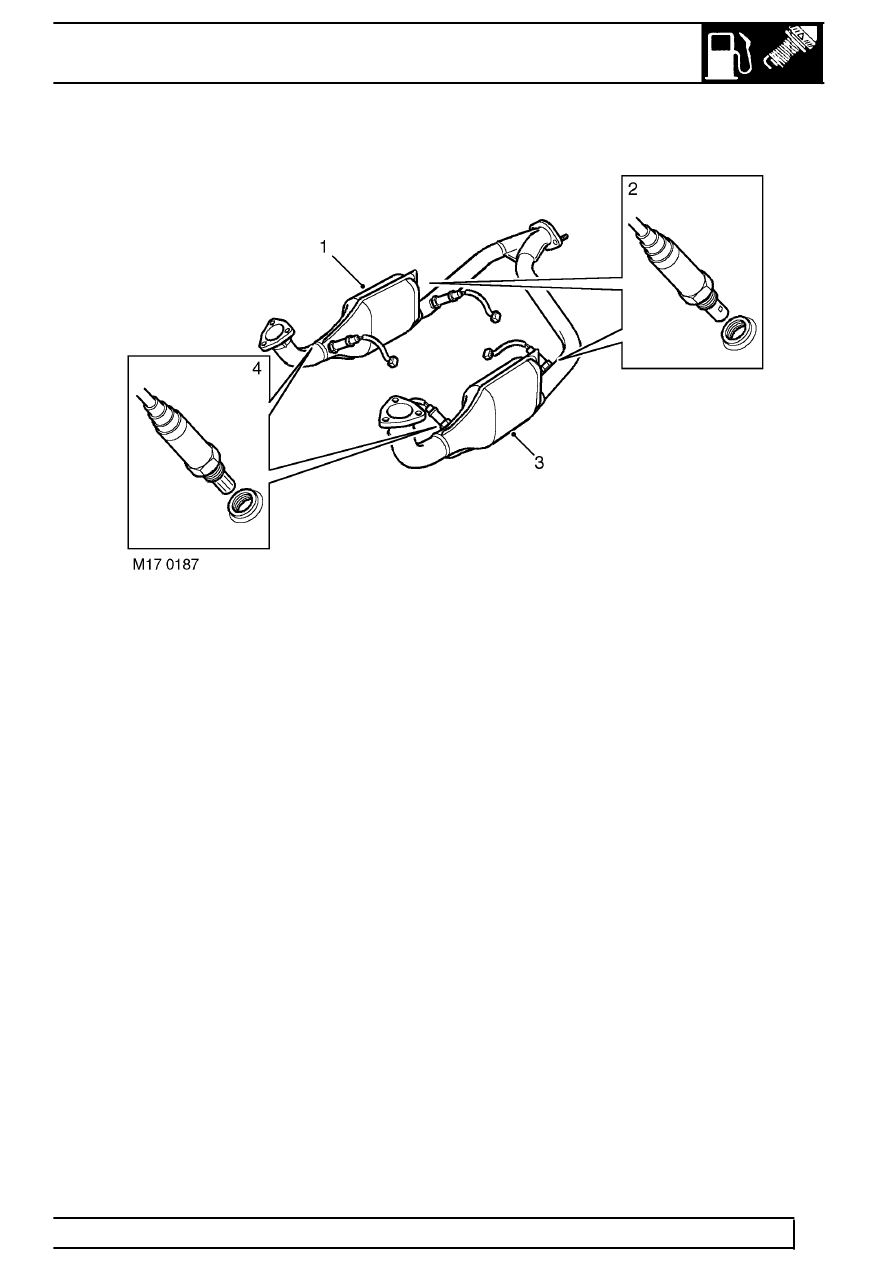
1. RH catalytic converter
2. Heated oxygen sensors - post-catalytic converters (2 off - NAS only)
3. LH catalytic converter
4. Heated oxygen sensors - pre-catalytic converters (2 off)
The number of heated oxygen (HO
2
S) sensors fitted
to a vehicle is dependent on the particular market
requirements:
•
4 - HO
2
S sensors (NAS vehicles)
•
2 - HO
2
S (UK, European, Australia & Japan
vehicles)
•
0 - HO
2
S (Gulf & ROW vehicles)
The HO
2
S sensors monitor the level of oxygen in the
exhaust gases and the resulting data is used by the
ECM to control the air:fuel mixture to provide the most
efficient mix under all operating conditions. By
positioning a sensor in the stream of exhaust gases
from each bank of cylinders of the V8 engine enables
the ECM to control the fuelling on each bank
independently. This allows the ECM to provide more
accurate control of the air:fuel ratio and monitor
catalytic converter efficiency.
Two upstream sensors are utilised in markets where
closed loop fuelling is the only mandatory
requirement. For markets where closed loop fuelling
control is not mandatory, HO
2
S sensors are not
included.
NAS vehicles utilise four HO
2
S sensors, one upstream
of each catalyst and one downstream of each catalyst.
This arrangement is used to monitor catalytic
converter efficiency and so determine when a catalyst
is no longer working effectively. Obtaining catalytic
converter efficiency data is a mandatory requirement
of the ECM OBD strategy. The downstream sensors
also provide for long term fuelling adaptions.
The basic closed control loop comprises the engine
(controlled system), the heated oxygen sensors
(measuring elements) and the engine management
ECM (control) and the injectors and ignition
(actuators). Although other factors also influence the
calculations of the ECM, such as air flow, air intake
temperature and throttle position. Additionally, special
driving conditions are compensated for such as
starting, acceleration and full load.
From cold start the ECM runs an open loop strategy,
which is kept in place until the sensor’s working
temperature has been reached.