
Range Rover P38
MANIFOLD AND EXHAUST SYSTEM
3
REPAIR
Refit
18. Ensure mating faces are clean.
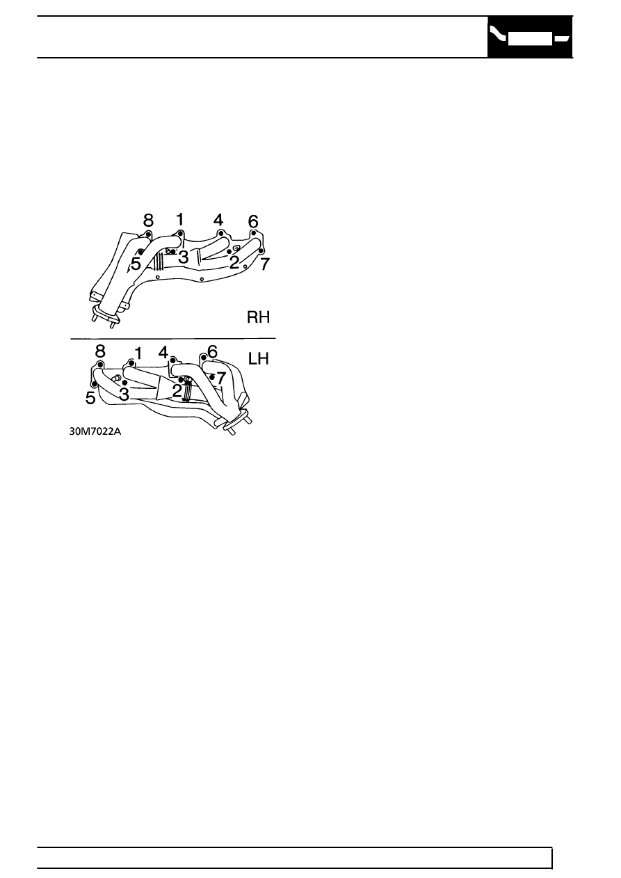
19. Position manifold on cylinder head. Align new
gaskets.
20. Secure manifold with bolts. Tighten to
55 Nm
(40 lbf.ft) in sequence shown.
21. Fit outer heat shield. Secure with bolts. Tighten
to
8 Nm (6 lbf.ft)
22. Position purge valve on shock absorber turret.
Secure with bolt.
23. Connect purge hose to ram pipe housing.
24. Fit air flow meter/hose assembly to plenum
chamber. Secure with clip.
25. Connect multiplug to air flow meter.
26. Fit ’O’ ring to air flow meter. Secure meter to air
cleaner with clips.
27. Engage harness in intake hose clip.
28. Tighten RH shock absorber top mounting bolt to
85 Nm (63 lbf.ft)
29. Position H.T. lead clip on rocker cover. Secure
with screw.
30. Route H.T. leads. Secure in clips. Connect plug
caps.
31. If removed, fit intermediate steering shaft.
See
STEERING, Repair.
32. Raise lift.
33. Fit new gasket to front pipe. Position pipe to
exhaust manifold. Secure with nuts. Tighten to
50 Nm (37 lbf.ft)
34. Reconnect battery negative lead.