Range Rover P38

75
SUPPLEMENTARY RESTRAINT SYSTEM
NEW RANGE ROVER
16
DESCRIPTION AND OPERATION
When a severe frontal impact is detected by the DCU,
electronic switches are closed causing a small
electrical current to be applied to the igniter squib. The
igniter is activated to produce heat and cause the gas
capsules to generate a propellant which forces a
piston up the cylinder. The piston draws a rack and
pinion mechanism which pulls back the seatbelt inertia
reel to hold the occupant securely in the seat in a
position suitable for airbag deployment. When the
rotor reaches the extent of its travel, excess propellant
is ejected to atmosphere via a port in the top of the
propellant tube.
WARNING: Once the pre-tensioner has
been operated, it cannot be reset. The
pinion locking pin will have been broken
and the gas generant will be exhausted. The unit
must be replaced.
Each pre-tensioner unit has a flying lead which
terminates in a yellow 2-pin connector that connects
to the DCU through the main harness. The
pre-tensioner to main harness connector is located
below the lower ’B’ post finisher.
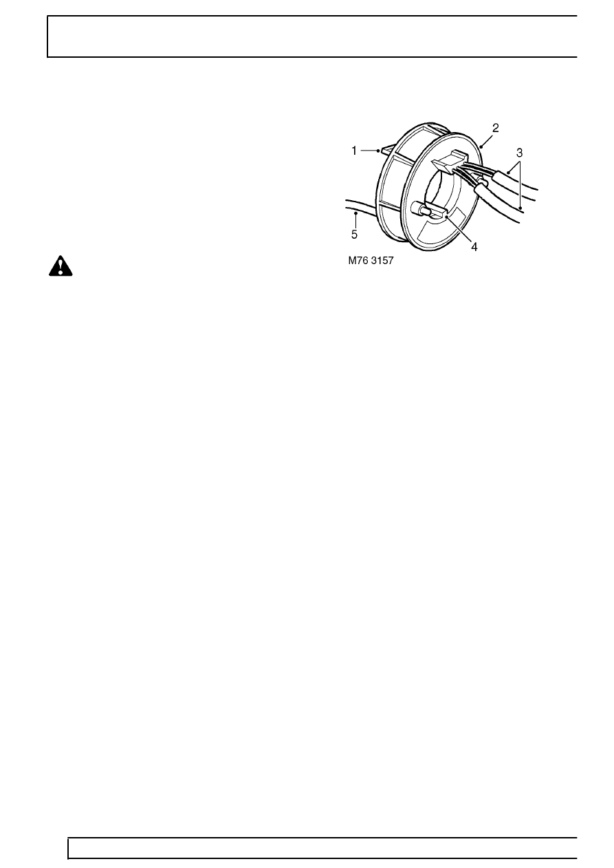
Rotary coupler
1. Securing clips
2. Outer housing
3. Electrical fly leads (to driver airbag module and
steering wheel switches)
4. Alignment key
5. Electrical flylead (to SRS and main harness)
The rotary coupler is installed on the steering column,
behind the steering wheel to provide the electrical
interface between the fixed wiring harness and the
moveable driver airbag module. In addition to the
wiring for the driver airbag, the rotary coupler also
provides the wiring for other electrical functions built
into the steering wheel area, these may include:
•
ICE system control switches
•
Cruise control system switches
•
Horn switches
A rotating link harness is encapsulated into a plastic
cassette comprising outer and inner housings with
integral connectors. The cassette contains a flat
ribbon type flexible cable with seven wires (not all the
wires are utilised on all vehicle derivatives). The rear
of the rotary coupler features two clips which align to
mating holes within the steering column die cast
bracket. The inner housing can turn a maximum of 4.2
revolutions in relation to the outer housing.
The rotary coupler connects the fascia harness to the
driver’s airbag module via a 2-way red connector
located below the steering column cowl.
