Range Rover P38

SUPPLEMENTARY RESTRAINT SYSTEM
15
DESCRIPTION AND OPERATION
When a severe side impact is detected by the DCU,
electronic switches are closed causing a small
electrical current to be supplied to the igniter squib in
the airbag on the side of the vehicle affected by the
impact. The activated igniter charge produces heat
causing the 3g of nitrocellulose to ignite and generate
nitrogen gas. The pressure of the expanding gas from
the nitrocellulose chamber punctures the port of the
nitrogen/argon gas chamber. The gas released from
the nitrogen/argon chamber is then mixed with the gas
from the nitrocellulose chamber in the central mixing
chamber. The resulting nitrogen gas escapes from
holes in the mixing chamber to rapidly fill the nylon
bag. The force of the inflating bag, forces the module
casing to split open and deploy the airbag through the
seat seam at the piping line.
The module is mounted at the outboard side bolster
seam of the seat squab, and the expanding airbag
initiates a seam thread failure in a designed and
controlled manner. Once free of the module housing
and seat cover, the nylon bag inflates to its full extent,
pushing the seat occupant away from the side of the
vehicle suffering the impact. When the bag is fully
inflated, vents in the airbag prevent further pressure
build-up and when the gas generation is exhausted,
the airbag begins to deflate. The side airbag has a
capacity of 12 litres.
NOTE: Side airbag modules must be
replaced at 15 year intervals.
NOTE: The front doors contain side impact
beams to help reduce intrusion of the
impact object and give additional
protection to the front seat occupants.
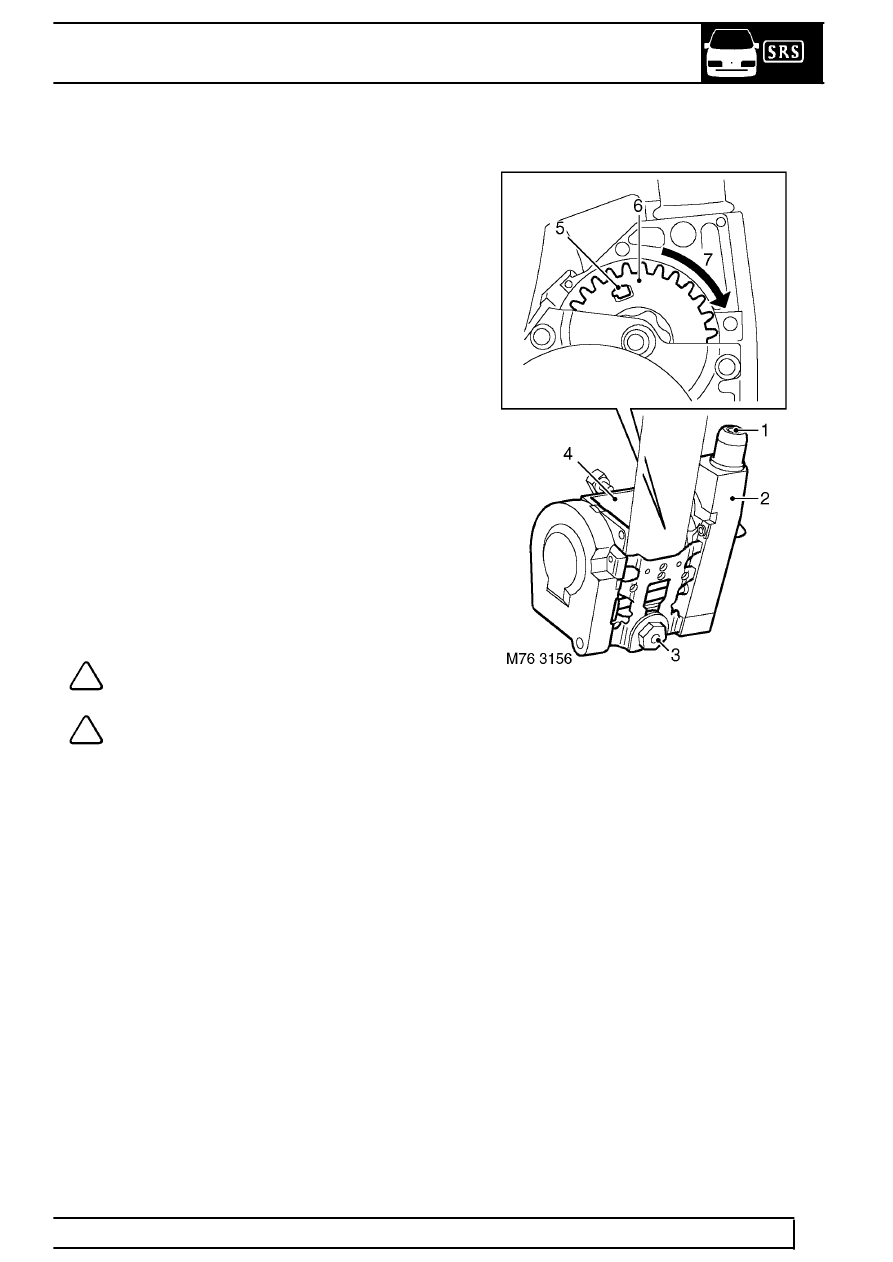
Seatbelt pre-tensioners
1. Exhaust port
2. Propellant tube
3. Inertia reel fixing bolt
4. Reel
5. Pinion locking tab
6. Pinion
7. Direction of rotation
During a frontal collision, the seat belt pre-tensioners
tighten the front seat belts to ensure the occupants
are securely held in their seats. The pre-tensioner
units are located with the seat belt inertia reel
assembly located at the bottom of the ’B’ post.
The seatbelt pre-tensioners are activated by a control
signal from the SRS DCU in the event of a frontal
collision. The two pre-tensioners are handed, but are
otherwise identical. Each of the pre-tensioner units is
fitted with an igniter and a propellant generator which
acts on a rotor which is attached to the seatbelt inertia
reel.
