
Coolant temperature gauge reading high
- Make
- Land Rover
- Model
- Range Rover P38 Technical Bulletins
- Section
- Coolant temperature gauge reading high › Coolant temperature gauge reading high
COOLANT TEMPERATURE GAUGE READING HIGH
- Model
- Range Rover
- Affected vehicles
- All diesel derivatives - refer to ACTION text for specific change points. RE - ISSUE INFORMATION: Diagnostic procedures amended and details of an improved coolant temperature sensor added. Please destroy your existing copy and replace with this Issue 2.
- Date
- 1998-12-23
- Reference
- Bulletin 26, CDS ref 260296
Bulletin text
Range Rover
AFFECTED RANGE:
All diesel derivatives - refer to ACTION text for specific change points.
RE - ISSUE INFORMATION: Diagnostic procedures amended and details of an improved coolant temperature sensor added. Please destroy your existing copy and replace with this Issue 2.
PROBLEM:
COOLANT TEMPERATURE GAUGE READING HIGH
CAUSE:
Poor electrical earths and / or poor performance of the cooling system.
ACTION:
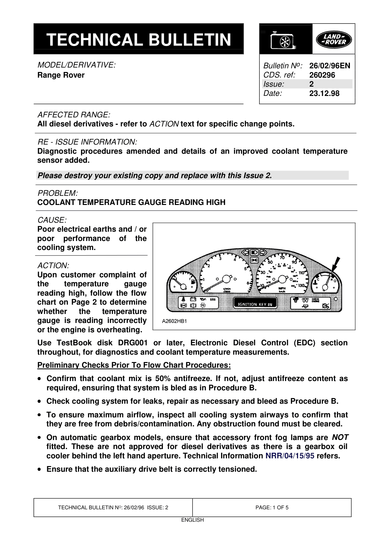
Upon customer complaint of the temperature gauge reading high, follow the flow chart on Page 2 to determine whether the temperature gauge is reading incorrectly or the engine is overheating. Use TestBook disk DRG001 or later, Electronic Diesel Control (EDC) section throughout, for diagnostics and coolant temperature measurements. Preliminary Checks Prior To Flow Chart Procedures: • = Confirm that coolant mix is 50% antifreeze. If not, adjust antifreeze content as required, ensuring that system is bled as in Procedure B. • = Check cooling system for leaks, repair as necessary and bleed as Procedure B. • = To ensure maximum airflow, inspect all cooling system airways to confirm that they are free from debris/contamination. Any obstruction found must be cleared. • = On automatic gearbox models, ensure that accessory front fog lamps are NOT fitted. These are not approved for diesel derivatives as there is a gearbox oil cooler behind the left hand aperture. Technical Information NRR/04/15/95 refers. • = Ensure that the auxiliary drive belt is correctly tensioned.
Bulletin N o : 26/02/96EN 260296 2 23.12.98
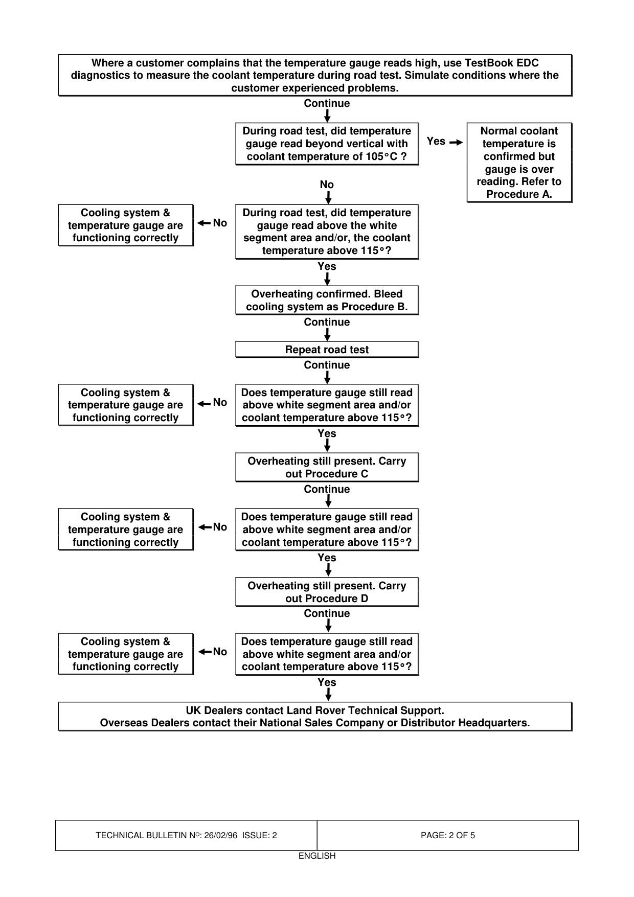
Where a customer complains that the temperature gauge reads high, use TestBook EDC diagnostics to measure the coolant temperature during road test. Simulate conditions where the customer experienced problems.
During road test, did temperature gauge read beyond vertical with coolant temperature of 105 Γ C ?
Cooling system & During road test, did temperature No temperature gauge are gauge read above the white functioning correctly segment area and/or, the coolant temperature above 115 Γ ?
Overheating confirmed. Bleed cooling system as Procedure B.
Does temperature gauge still read Cooling system & No temperature gauge are above white segment area and/or functioning correctly coolant temperature above 115 Γ ?
Overheating still present. Carry
Does temperature gauge still read Cooling system & No temperature gauge are above white segment area and/or functioning correctly coolant temperature above 115 Γ ?
Overheating still present. Carry
Does temperature gauge still read Cooling system & No temperature gauge are above white segment area and/or functioning correctly coolant temperature above 115 Γ ?
UK Dealers contact Land Rover Technical Support. Overseas Dealers contact their National Sales Company or Distributor Headquarters.
Continue
Normal coolant Yes temperature is confirmed but gauge is over reading. Refer to No Procedure A.
Yes
Continue
Repeat road test Continue
Yes
out Procedure C Continue
Yes
out Procedure D Continue
Yes
Procedure A: Temperature Gauge Inaccurate
A1. Ensure earth points at BECM, BECM body earth, main body earth (below underbonnet fusebox) and engine earths are clean and tight. Refer to Technical Information NRR/86/03/96 for earth point location and rectification details.
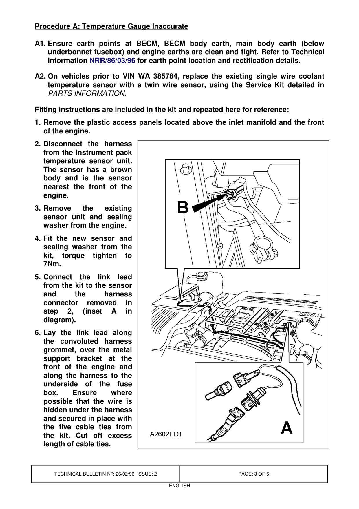
A2. On vehicles prior to VIN WA 385784, replace the existing single wire coolant temperature sensor with a twin wire sensor, using the Service Kit detailed in PARTS INFORMATION . = Fitting instructions are included in the kit and repeated here for reference: 1. Remove the plastic access panels located above the inlet manifold and the front of the engine. 2. Disconnect the harness from the instrument pack temperature sensor unit. The sensor has a brown body and is the sensor nearest the front of the engine. 3. Remove the existing sensor unit and sealing washer from the engine. 4. Fit the new sensor and sealing washer from the kit, torque tighten to 7Nm. 5. Connect the link lead from the kit to the sensor and the harness connector removed in step 2, (inset A in diagram). 6. Lay the link lead along the convoluted harness grommet, over the metal support bracket at the front of the engine and along the harness to the underside of the fuse box. Ensure where possible that the wire is hidden under the harness and secured in place with the five cable ties from the kit. Cut off excess length of cable ties.
7. Secure the eyelet to the engine harness earth stud located under the fuse box (B in diagram) and tighten the nut to 7Nm. Do not secure to the main body earth eyelet.
8. Start the engine, warm up and confirm correct operation of gauge and that there are no coolant leaks.
9. Replace panels that were removed in step 1.
Procedure B: Cooling System Bleed
1. Remove expansion tank cap.
2. Disconnect radiator bleed hose.
3. Blow through the bleed hose detached from radiator and start to fill cooling system at expansion tank. When a steady flow comes from the bleed hose stub on the radiator, refit the bleed hose and continue filling until coolant is level with the base of the expansion tank filler neck.
4. Start engine, continue filling at the expansion tank until coolant level is stabilised at the ‘COLD’ level mark.
5. Run engine until the thermostat opens, (top hose becomes warm).
6. With engine idling, disconnect the bleed hose from the radiator and allow coolant to flow until all trace of air within coolant has disappeared. Refit the bleed hose.
7. Stop engine and allow to cool.
8. Check coolant level, top up as necessary.
9. Refit expansion tank filler cap.
Procedure C: Radiator Baffle Check
Tools required - torch and dental mirror or similar.
1. Drain radiator
2. Remove inlet and outlet hoses from radiator.
3. Insert mirror into either the radiator inlet or outlet stub and the torch into the other.
4. Angle mirror until a plastic baffle plate can be seen which will be translucent with reflected light.
If the baffle plate cannot be seen as described but a bright light from the torch is seen, the baffle plate is missing. This will require the radiator to be replaced.
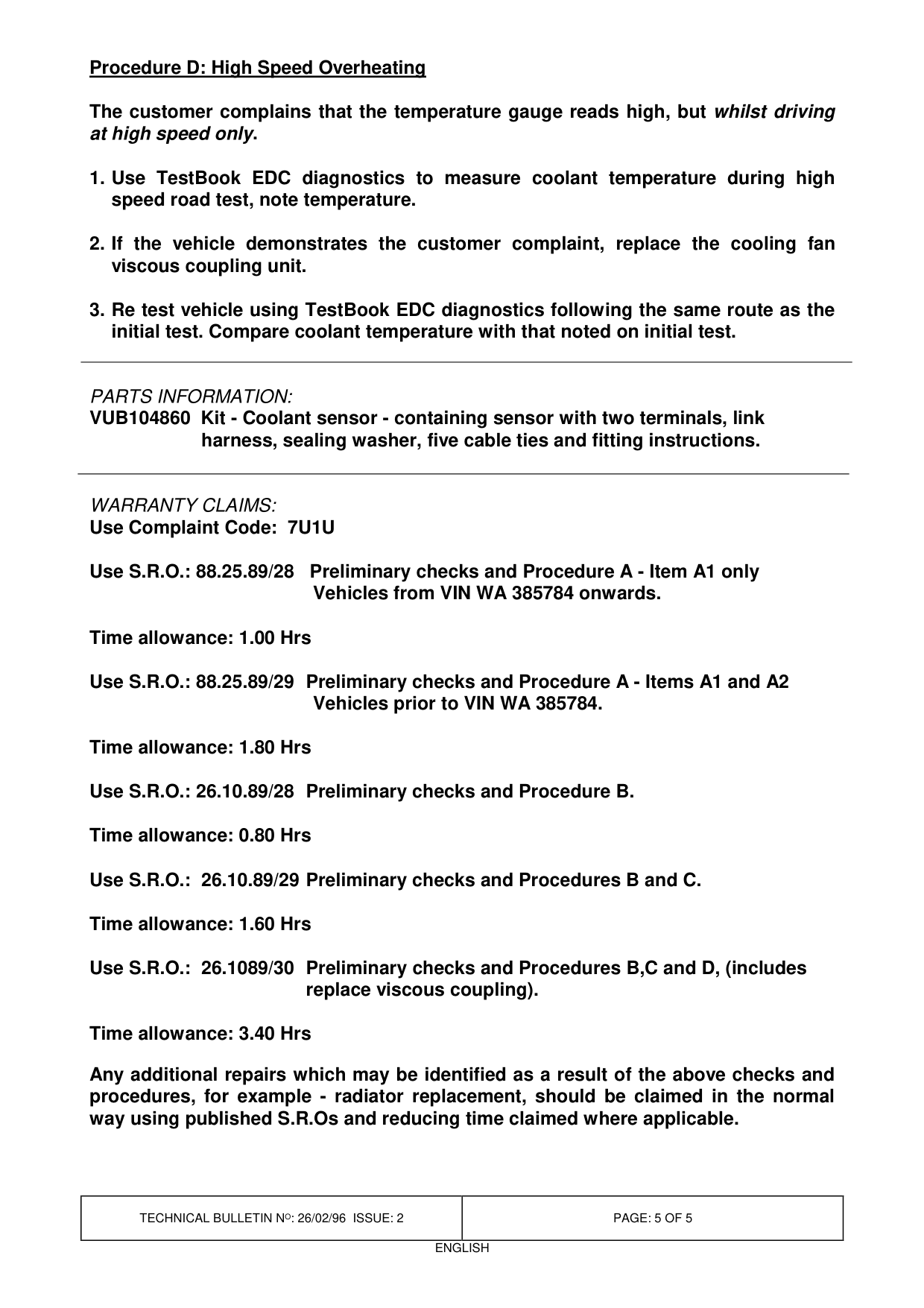
Procedure D: High Speed Overheating
The customer complains that the temperature gauge reads high, but whilst driving at high speed only.
1. Use TestBook EDC diagnostics to measure coolant temperature during high speed road test, note temperature.
2. If the vehicle demonstrates the customer complaint, replace the cooling fan viscous coupling unit.
3. Re test vehicle using TestBook EDC diagnostics following the same route as the initial test. Compare coolant temperature with that noted on initial test.
PARTS INFORMATION:
VUB104860 Kit - Coolant sensor - containing sensor with two terminals, link harness, sealing washer, five cable ties and fitting instructions.
WARRANTY CLAIMS: Use Complaint Code: 7U1U
Use S.R.O.: 88.25.89/28 Preliminary checks and Procedure A - Item A1 only Vehicles from VIN WA 385784 onwards.
Time allowance: 1.00 Hrs
Use S.R.O.: 88.25.89/29 Preliminary checks and Procedure A - Items A1 and A2 Vehicles prior to VIN WA 385784.
Time allowance: 1.80 Hrs
Use S.R.O.: 26.10.89/28 Preliminary checks and Procedure B.
Time allowance: 0.80 Hrs
Use S.R.O.: 26.10.89/29 Preliminary checks and Procedures B and C.
Time allowance: 1.60 Hrs
Use S.R.O.: 26.1089/30 Preliminary checks and Procedures B,C and D, (includes replace viscous coupling).
Time allowance: 3.40 Hrs
Any additional repairs which may be identified as a result of the above checks and procedures, for example - radiator replacement, should be claimed in the normal way using published S.R.Os and reducing time claimed where applicable.
Parts & tools for this job For Land Rover Range Rover
- FLUIDCoolantSearch: Land Rover coolant antifreeze
- PARTThermostatSearch: Land Rover Range Rover thermostat
- TOOLCooling system pressure testerSearch: cooling system pressure tester
Links open Amazon search results in a new tab. As an Amazon Associate I earn from qualifying purchases.