
Radio-poor am reception/interference
- Make
- Land Rover
- Model
- Range Rover P38 Technical Bulletins
- Section
- Radio-poor am reception/interference › Radio-poor am reception/interference
RADIO-POOR AM RECEPTION/INTERFERENCE
- Model
- New Range Rover
- Affected vehicles
- All
- Date
- 1997-02-21
- Reference
- 21/02/97
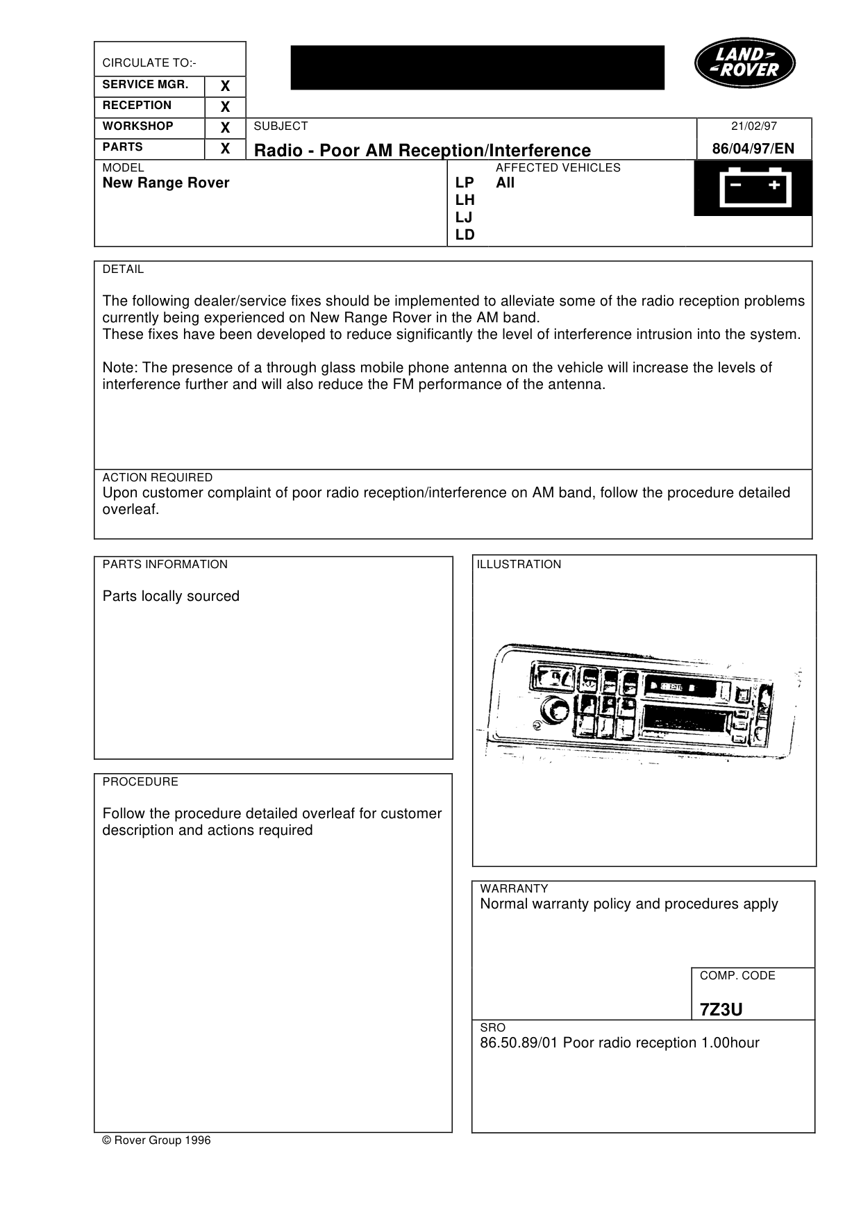
Bulletin text
Radio - Poor AM Reception/Interference
MODEL
New Range Rover
DETAIL
The following dealer/service fixes should be implemented to alleviate some of the radio reception problems currently being experienced on New Range Rover in the AM band. These fixes have been developed to reduce significantly the level of interference intrusion into the system.
Note: The presence of a through glass mobile phone antenna on the vehicle will increase the levels of interference further and will also reduce the FM performance of the antenna.
ACTION REQUIRED
Upon customer complaint of poor radio reception/interference on AM band, follow the procedure detailed overleaf.
PARTS INFORMATION
Parts locally sourced
PROCEDURE
Follow the procedure detailed overleaf for customer description and actions required
© Rover Group 1996
21/02/97
86/04/97/EN
AFFECTED VEHICLES
LP All LH LJ LD
WARRANTY
Normal warranty policy and procedures apply
COMP. CODE
7Z3U
SRO
86.50.89/01 Poor radio reception 1.00hour
Radio - Poor AM Reception/Interference
MODEL
New Range Rover
Diversity antenna system Actions required:a) Fitment of Radio Earth braid lead. b) Fitment of Bonnet Braid lead. c) Fitment of Antenna amplifier Earth lead. d) Swapping of Antenna amplifiers from right to left.
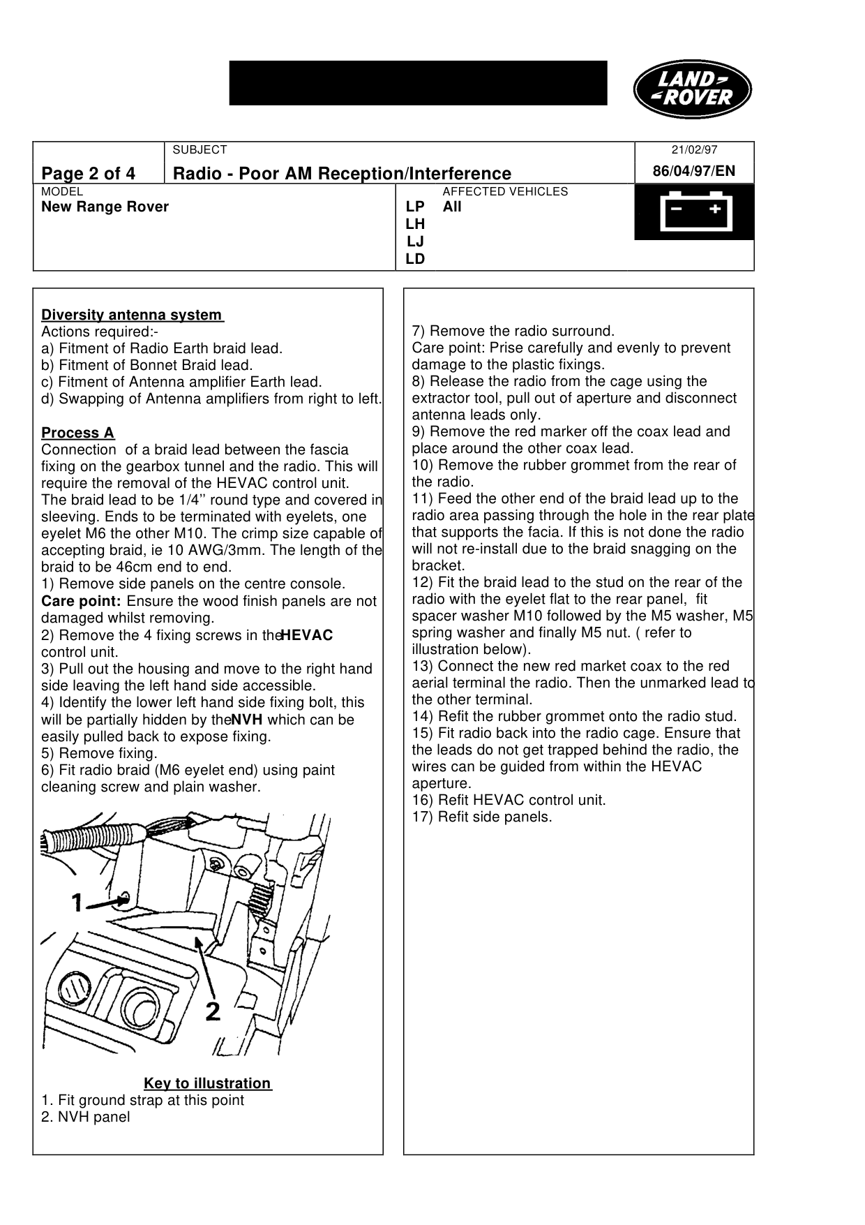
Process A Connection of a braid lead between the fascia fixing on the gearbox tunnel and the radio. This will require the removal of the HEVAC control unit. The braid lead to be 1/4’’ round type and covered in sleeving. Ends to be terminated with eyelets, one eyelet M6 the other M10. The crimp size capable of accepting braid, ie 10 AWG/3mm. The length of the braid to be 46cm end to end. 1) Remove side panels on the centre console. Care point: Ensure the wood finish panels are not damaged whilst removing. 2) Remove the 4 fixing screws in the HEVAC control unit. 3) Pull out the housing and move to the right hand side leaving the left hand side accessible. 4) Identify the lower left hand side fixing bolt, this will be partially hidden by the NVH which can be easily pulled back to expose fixing. 5) Remove fixing. 6) Fit radio braid (M6 eyelet end) using paint cleaning screw and plain washer.
Key to illustration 1. Fit ground strap at this point 2. NVH panel
21/02/97 86/04/97/EN
AFFECTED VEHICLES
LP All LH LJ LD
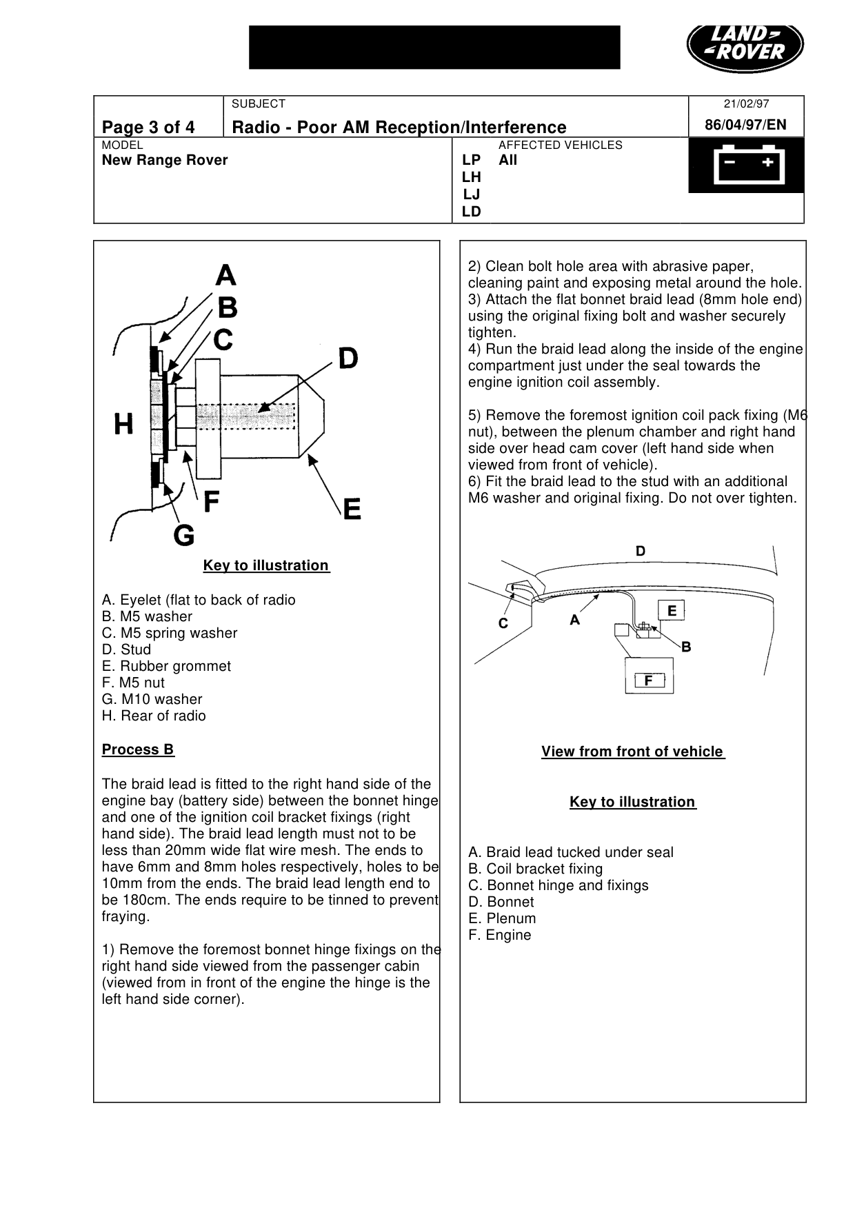
7) Remove the radio surround. Care point: Prise carefully and evenly to prevent damage to the plastic fixings. 8) Release the radio from the cage using the extractor tool, pull out of aperture and disconnect antenna leads only. 9) Remove the red marker off the coax lead and place around the other coax lead. 10) Remove the rubber grommet from the rear of the radio. 11) Feed the other end of the braid lead up to the radio area passing through the hole in the rear plate that supports the facia. If this is not done the radio will not re-install due to the braid snagging on the bracket. 12) Fit the braid lead to the stud on the rear of the radio with the eyelet flat to the rear panel, fit spacer washer M10 followed by the M5 washer, M5 spring washer and finally M5 nut. ( refer to illustration below). 13) Connect the new red market coax to the red aerial terminal the radio. Then the unmarked lead to the other terminal. 14) Refit the rubber grommet onto the radio stud. 15) Fit radio back into the radio cage. Ensure that the leads do not get trapped behind the radio, the wires can be guided from within the HEVAC aperture. 16) Refit HEVAC control unit. 17) Refit side panels.
Radio - Poor AM Reception/Interference
MODEL
New Range Rover
Key to illustration
A. Eyelet (flat to back of radio B. M5 washer C. M5 spring washer D. Stud E. Rubber grommet F. M5 nut G. M10 washer H. Rear of radio
Process B
The braid lead is fitted to the right hand side of the engine bay (battery side) between the bonnet hinge and one of the ignition coil bracket fixings (right hand side). The braid lead length must not to be less than 20mm wide flat wire mesh. The ends to have 6mm and 8mm holes respectively, holes to be 10mm from the ends. The braid lead length end to be 180cm. The ends require to be tinned to prevent fraying.
1) Remove the foremost bonnet hinge fixings on the right hand side viewed from the passenger cabin (viewed from in front of the engine the hinge is the left hand side corner).
21/02/97 86/04/97/EN
AFFECTED VEHICLES
LP All LH LJ LD
2) Clean bolt hole area with abrasive paper, cleaning paint and exposing metal around the hole. 3) Attach the flat bonnet braid lead (8mm hole end) using the original fixing bolt and washer securely tighten. 4) Run the braid lead along the inside of the engine compartment just under the seal towards the engine ignition coil assembly.
5) Remove the foremost ignition coil pack fixing (M6 nut), between the plenum chamber and right hand side over head cam cover (left hand side when viewed from front of vehicle). 6) Fit the braid lead to the stud with an additional M6 washer and original fixing. Do not over tighten.
View from front of vehicle
Key to illustration
A. Braid lead tucked under seal B. Coil bracket fixing C. Bonnet hinge and fixings D. Bonnet E. Plenum F. Engine
Radio - Poor AM Reception/Interference
MODEL
New Range Rover
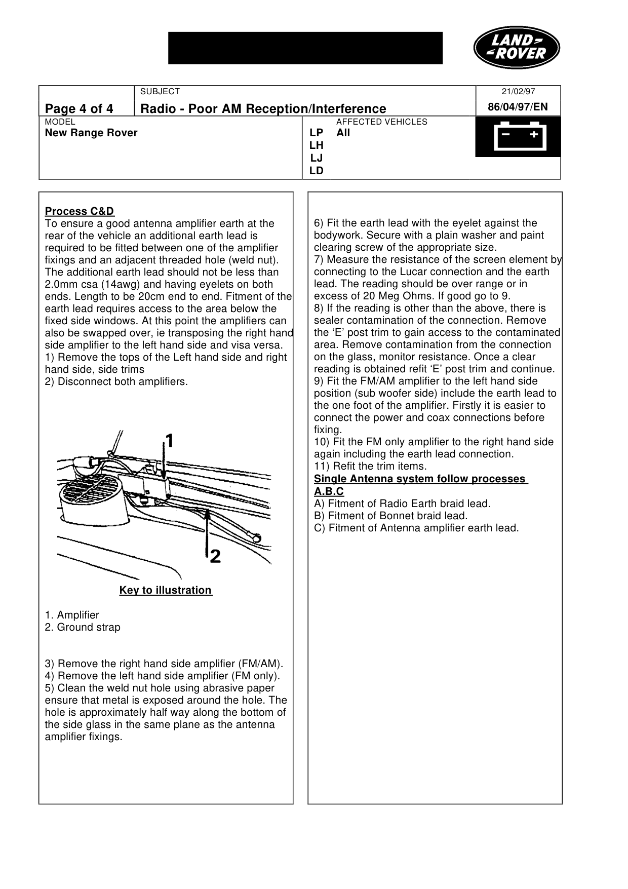
Process C&D To ensure a good antenna amplifier earth at the rear of the vehicle an additional earth lead is required to be fitted between one of the amplifier fixings and an adjacent threaded hole (weld nut). The additional earth lead should not be less than 2.0mm csa (14awg) and having eyelets on both ends. Length to be 20cm end to end. Fitment of the earth lead requires access to the area below the fixed side windows. At this point the amplifiers can also be swapped over, ie transposing the right hand side amplifier to the left hand side and visa versa. 1) Remove the tops of the Left hand side and right hand side, side trims 2) Disconnect both amplifiers.
Key to illustration
1. Amplifier 2. Ground strap
3) Remove the right hand side amplifier (FM/AM). 4) Remove the left hand side amplifier (FM only). 5) Clean the weld nut hole using abrasive paper ensure that metal is exposed around the hole. The hole is approximately half way along the bottom of the side glass in the same plane as the antenna amplifier fixings.
21/02/97 86/04/97/EN
AFFECTED VEHICLES
LP All LH LJ LD
6) Fit the earth lead with the eyelet against the bodywork. Secure with a plain washer and paint clearing screw of the appropriate size. 7) Measure the resistance of the screen element by connecting to the Lucar connection and the earth lead. The reading should be over range or in excess of 20 Meg Ohms. If good go to 9. 8) If the reading is other than the above, there is sealer contamination of the connection. Remove the ‘E’ post trim to gain access to the contaminated area. Remove contamination from the connection on the glass, monitor resistance. Once a clear reading is obtained refit ‘E’ post trim and continue. 9) Fit the FM/AM amplifier to the left hand side position (sub woofer side) include the earth lead to the one foot of the amplifier. Firstly it is easier to connect the power and coax connections before fixing. 10) Fit the FM only amplifier to the right hand side again including the earth lead connection. 11) Refit the trim items. Single Antenna system follow processes A.B.C A) Fitment of Radio Earth braid lead. B) Fitment of Bonnet braid lead. C) Fitment of Antenna amplifier earth lead.
Parts & tools for this job For Land Rover Range Rover
- TOOLDigital multimeterSearch: automotive digital multimeter
- PARTAssorted fuse kitSearch: car fuse assortment kit
- TOOLWire crimper and connector kitSearch: wire crimper connector kit
Links open Amazon search results in a new tab. As an Amazon Associate I earn from qualifying purchases.