
Track rod/drag link repair procedure
- Make
- Land Rover
- Model
- Range Rover P38 Technical Bulletins
- Section
- Track rod/drag link repair procedure › Track rod/drag link repair procedure
TRACK ROD/DRAG LINK REPAIR PROCEDURE
- Model
- New Range Rover
- Affected vehicles
- All
- Date
- 1995-09-20
- Reference
- 20/09/95
Bulletin text
Track Rod/Drag Link Repair Procedure
MODEL
New Range Rover
DETAIL
During final pit inspection it was found that the large adjuster clamp bolts on the track rod and drag link had more than 3 full threads protruding through the nut, investigations have found that the clamp is bending, due to a material issue and the torque figure being too high, the torque figure has been revised from 47Nm to 3236 Nm to elelate any further concerns.
ACTION REQUIRED
On Pre-Delivery Inspection or at the regular service interval check the track rod/drag link clamp, if more than 3 threads are protruding through the nuts, follow the procedure detailed below.
PARTS INFORMATION
STC 3107 Clamp Kit
PROCEDURE
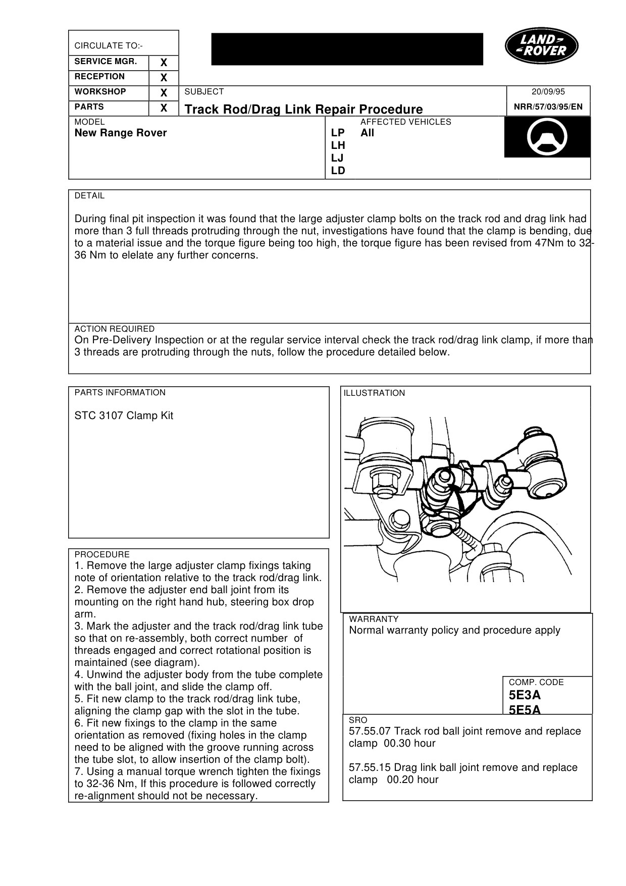
1. Remove the large adjuster clamp fixings taking note of orientation relative to the track rod/drag link. 2. Remove the adjuster end ball joint from its mounting on the right hand hub, steering box drop arm. 3. Mark the adjuster and the track rod/drag link tube so that on re-assembly, both correct number of threads engaged and correct rotational position is maintained (see diagram). 4. Unwind the adjuster body from the tube complete with the ball joint, and slide the clamp off. 5. Fit new clamp to the track rod/drag link tube, aligning the clamp gap with the slot in the tube. 6. Fit new fixings to the clamp in the same orientation as removed (fixing holes in the clamp need to be aligned with the groove running across the tube slot, to allow insertion of the clamp bolt). 7. Using a manual torque wrench tighten the fixings to 32-36 Nm, If this procedure is followed correctly re-alignment should not be necessary.
20/09/95
NRR/57/03/95/EN
AFFECTED VEHICLES
LP All LH LJ LD
WARRANTY
Normal warranty policy and procedure apply
COMP. CODE
5E3A 5E5A
SRO
57.55.07 Track rod ball joint remove and replace clamp 00.30 hour
57.55.15 Drag link ball joint remove and replace clamp 00.20 hour
Parts & tools for this job For Land Rover Range Rover
- TOOLTie rod end toolSearch: tie rod end puller
- TOOLBall joint separatorSearch: ball joint separator
- FLUIDPower steering fluidSearch: Land Rover power steering fluid
Links open Amazon search results in a new tab. As an Amazon Associate I earn from qualifying purchases.