
76 - CHASSIS AND BODY (page 2 of 4)
- Make
- Land Rover
- Model
- Range Rover Classic
CHASSIS AND BODY
73
REPAIR
ADD: 09/95
7. Remove RH ’A’ post finisher.
8. Remove header finisher.
9. Apply masking tape to protect paint finish around
glass.
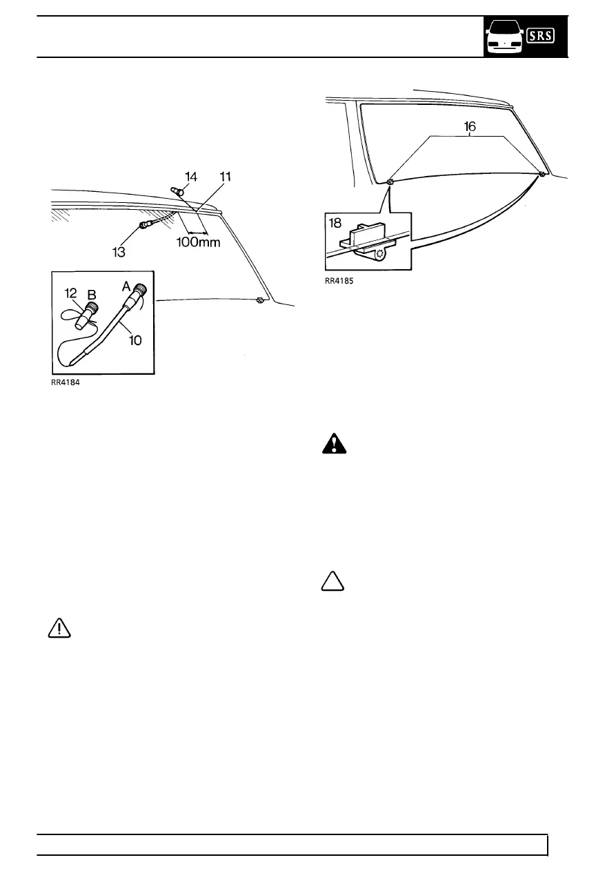
10. Prepare cutting wire in handle ’A’. Bend end of
wire to handle and tape over end.
11. Force cutting wire through sealer from inside and
100mm from a top corner. Use a needle if
necessary to make a pilot hole.
12. Attach handle ’B’. Allow 200mm of wire between
handles, tape over end of wire.
13. With an assistant on the inside: Wedge the
tube of the handle ’A’ between glass and body
flange 100mm ahead of hole in sealer.
14. From the outside: Carefully cut sealer from
flange using a straight pull away from the glass.
Continue in 100mm steps around the glass, use
a sawing action at the corners.
CAUTION: Along the bottom edge, great
care must be taken to cut up to the 2
supports, positions indicated on the
obscuration band (See item 18).
15. Remove handle ’B’, withdraw the cutting wire
and insert it through the sealer between the
supports. Refit handle ’B’.
16. Cut through sealer between the supports.
If heated front screen: Cut through the 2 wires
each side of the supports. Tape cut wires and
panels to prevent damage to bodywork when
screen is removed.
17. Attach suction cups to glass and lift glass from
body flange, cut sealer free around supports as
necessary.
WARNING: If glass has splintered: Protect
eyes and operate demister blower at
maximum speed to remove any glass from
ducts. Use a vacuum cleaner to remove glass
particles from inside the vehicle.
Refit
18. Check condition of supports, renew if necessary.
Locating studs must be at right angle to flange.
NOTE: The supports were fitted to early
vehicles and now replaced with nylon
sheaths.
19. Carefully cut back old sealant around body
flange to obtain a smooth surface 2mm thick. DO
NOT cut down to flange.
20. If refitting original glass: It must be free from
chips or cracks. Cut back old sealant around
glass to obtain a smooth surface 2mm thick. DO
NOT cut down to glass surface.
Parts & tools for this job For Land Rover Range Rover
- TOOLTrim removal tool kitSearch: trim removal tool kit
- PARTTouch-up paintSearch: Land Rover touch up paint
- PARTPanel clip assortmentSearch: Land Rover panel clips assortment
Links open Amazon search results in a new tab. As an Amazon Associate I earn from qualifying purchases.