Engine Overhaul Manual v8 40 46: Description and Operation

ENGINE
DESCRIPTION AND OPERATION
7
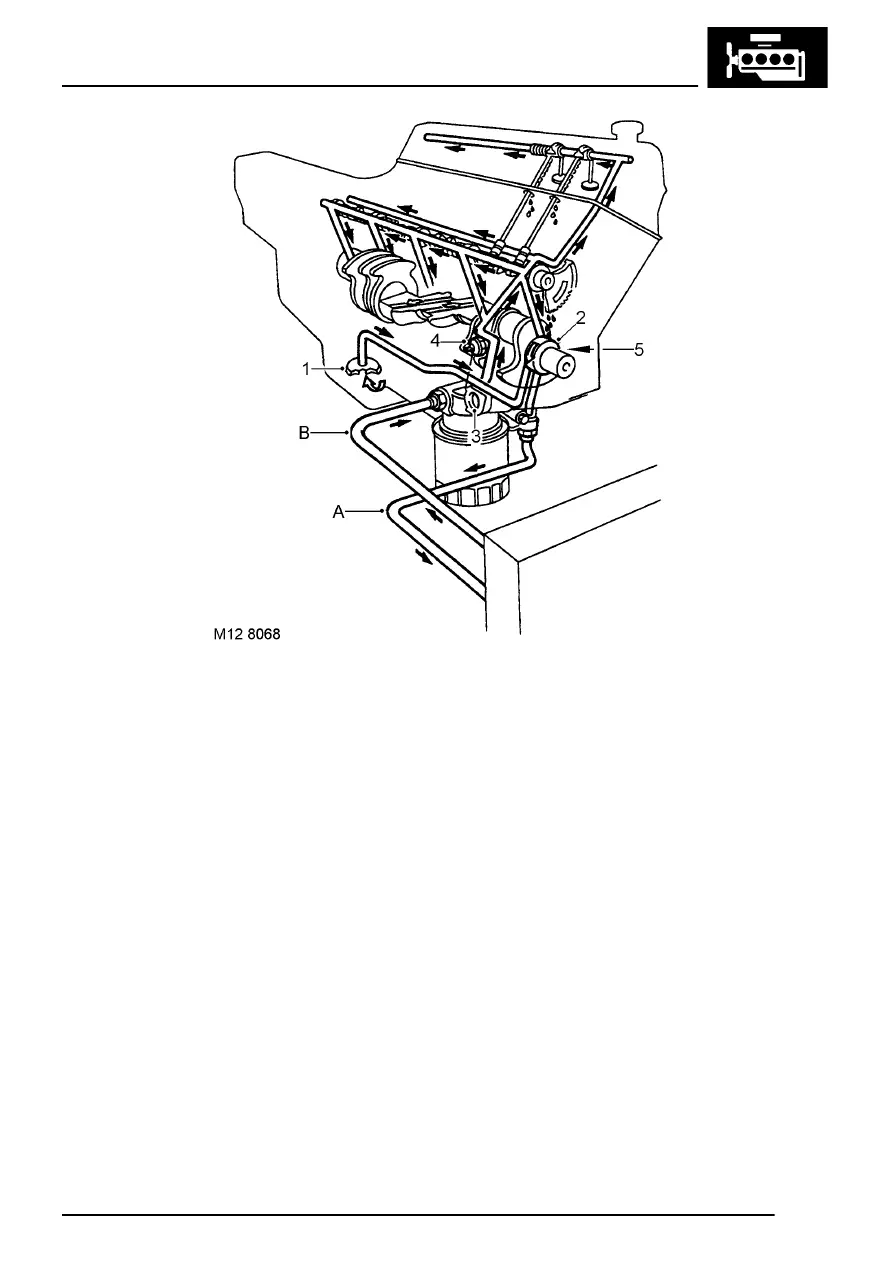
1. Oil strainer
2. Oil pump
3. Oil pressure by-pass valve
4. Oil pressure switch
5. Oil pressure relief valve - if fitted
A Oil to cooler - if fitted
B Oil from cooler - if fitted
Lubrication
The full flow lubrication system uses a gear type oil
pump driven from the crankshaft. The assembly is
integral with the timing cover which also carries the
full flow oil filter, oil pressure switch, oil pressure
by-pass valve and oil pressure relief valve - if fitted.
Oil is drawn from the pressed steel sump through a
strainer and into the oil pump, excess pressure
being relieved by the pressure relief valve. The oil
pressure warning light switch is screwed into the
timing cover and registers the oil pressure in the
main oil gallery on the outflow side of the filter.
Pressurised oil passes through an oil cooler - if fitted
mounted in front of the radiator to the full flow oil
filter. The oil then passes through internal drillings to
the crankshaft where it is directed to each main
bearing and to the big end bearings via numbers 1,
3 and 5 main bearings.
An internal drilling in the cylinder block directs oil to
the camshaft where it passes through further internal
drillings to the hydraulic tappets, camshaft journals
and rocker shaft. Lubrication to the thrust side of the
cylinders is either by oil grooves machined in each
connecting rod big end joint face or by splash.
