Engine Overhaul Manual: Description and Operation - How It Works

ENGINE
6
DESCRIPTION AND OPERATION
OPERATION
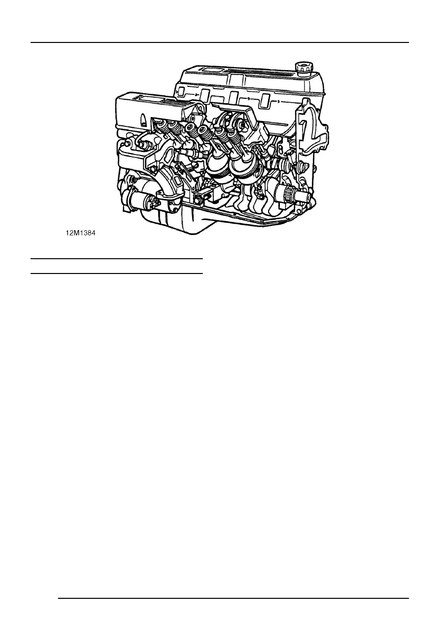
The V8 engine is an eight cylinder, water cooled unit
comprising cast aluminium cylinder block and
cylinder heads.
The cast iron cylinder liners are shrink fitted and
located on stops in the cylinder block. The banks of
cylinders are at 90
°
to each other. The crankshaft is
carried in five main bearings, end-float being
controlled by the thrust faces of the upper centre
main bearing shell.
The centrally located camshaft is driven by the
crankshaft via a chain. The valves are operated by
rockers, pushrods and hydraulic tappets. Exhaust
valves used on later engines are of the ’carbon
break’ type which incorporate a machined undercut
at the combustion chamber end of the valve. The
design prevents carbon build-up on the valve stem
which could lead to valves sticking. These valves
are interchangeable with valves fitted to early
engines provided that the latest valve guides which
are 5 mm (0.2 in) than those fitted to early engines
are also fitted.
Each of the aluminium alloy pistons has two
compression rings and an oil control ring. The
pistons are secured to the connecting rods by
semi-floating gudgeon pins. The gudgeon pin is
offset 0.5 mm (0.02 in), identified by an arrow mark
on the piston crown, which must always point to the
front of the engine. Plain, big-end bearing shells are
fitted to each connecting rod.
