Engine Overhaul Manual v8 4.0 4.6

ENGINE
OVERHAUL
9
7. Check valve stem to guide clearance D using
the following procedures:
8. Insert each valve into its respective guide.
9. Extend valve head approximately 13 mm (0.6
in) out of valve seat and position a suitable dial
test indicator to rear of valve head.
10. Move valve towards front of cylinder head and
zero dial test indicator gauge ensuring that
stylus of gauge remains in contact with valve
head.
11. Move valve towards rear of cylinder head and
record gauge reading to give valve stem to
guide clearance:
Inlet valves - Early and later engines = 0.025 to
0.066 mm (0.001 to 0.002 in)
Exhaust valves:
Standard and carbon break exhaust valves
fitted to early engines = 0.038 to 0.078 mm
(0.0015 to 0.003 in)
Modified carbon break exhaust valves fitted to
later engines = 0.048 to 0.088 mm (0.0019 to
0.0035 in)
12. Repeat above procedures for each valve in
turn.
13. Renew valves, guides and valve seat inserts
as necessary.
CAUTION: If modified valves and guides
are to be fitted, they must be replaced in
engine sets.
14. Check condition of valve springs:
Free length = 48.30 mm (1.90 in)
Fitted length = 40.40 mm (1.60 in)
Load - valve closed = 339
±
10 N (76
±
2 lbf)
Load - valve open = 736
±
10 N (165
±
2 lbf)
NOTE: Valve springs must be replaced as
a complete set.
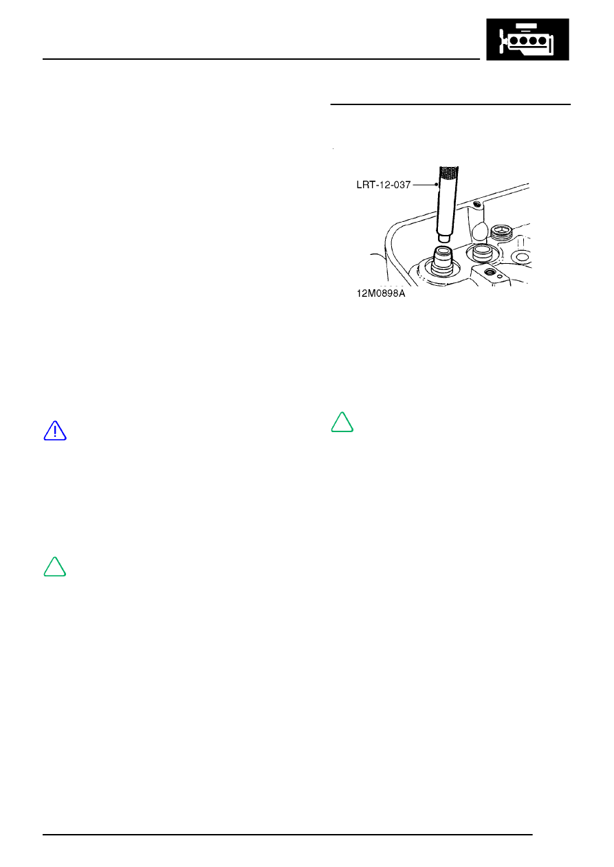
Valve guides - renew
1. Using valve guide remover, LRT-12-037 press
valve guide out into combustion face side of
cylinder head.
NOTE: Service valve guides are 0.025 mm
(0.001 in) oversize on outside diameter to
ensure interference fit.
2. Lubricate new valve guide with engine oil,
position guide with tapered portion leading to
valve spring side of cylinder head.
