
Seats
- Make
- Lincoln
- Model
- Town Car Factory Service Manual
- Year
- 2007
- Section
- 501-10 Seating › Diagnosis and testing › Seats
Seats
 |
Fluke 73 III Automotive Meter
105-R0051 |
 |
Vehicle Communication Module (VCM) and Integrated Diagnostic System (IDS) software with appropriate hardware, or equivalent scan tool
|
 |
Diagnostic Tool, Restraint System (2 required)
418-133 (014-R1076) |
Restraint System Diagnostic Tool Warning
WARNING: The restraint system diagnostic tool is for restraint system service only. Remove from vehicle prior to road use. Failure to remove could result in injury and possible violation of vehicle safety standards.
Principles of Operation
Front Power Seats
The driver and front passenger power seat motors are hardwired to the seat control switches on each respective front door trim panel. The circuits are normally at ground through the seat control switch. Each individual seat track or recliner motor circuit (if equipped) is switched to power when the specific adjustment position is selected.
Memory Seat
The driver power seat is controlled by the driver seat module (DSM). The driver seat control switch circuits are connected to inputs on the driver door module (DDM) and apply fused battery voltage to the DDM inputs. The DDM communicates the seat control switch position by transmitting signal data to the DSM using the SCP communication bus. The received signal data causes the DSM to apply power directly to the appropriate seat motor. Toggling the seat control switch in the opposite direction changes the input to the DDM and the signal transmitted to the DSM causing it to apply power to the opposite seat motor circuit. Ground is the normal state of the motor circuits through the DSM. The DSM internally switches the appropriate circuit from ground to power to adjust the motors.
As the seat is adjusted, the DSM constantly monitors the motor position sensors to record the current seat position. The DSM will remove power from the motor upon termination of the seat control switch input or if the DSM does not see movement from the motor by monitoring the seat position sensor.
Memory seat positioning can be recalled with the memory switches on the driver door panel or a programmed remote keyless entry transmitter. In either case, the DSM receives a memory recall 1 or 2 command from the DDM over the SCP communication network. The memory recall switches are a hardwired input to the DDM. The DDM also receives the remote keyless entry transmitter signals. Once a valid memory recall command is received from the DDM, the DSM moves the driver seat to the position stored in memory by powering the appropriate motors and monitoring the motor position sensors until the position is reached.
Heated Seats
Vehicles equipped with front heated seats are equipped with a heated seat module which controls both front heated seats. The heated seat module is located behind the front passenger door trim panel.
Vehicles equipped with rear heated seats are equipped with 2 rear heated seat modules, one for the left rear heated seat and the other for the right rear heated seat. Each rear heated seat module is located underneath the respective rear seat backrest trim cover.
The functionality of both the front and rear heated seat systems is similar. When the heated seat switch is pressed with the ignition switch in RUN, a momentary voltage signal is sent to the heated seat module. The heated seat module then supplies power to the heater circuit. The cushion heater mat and seat backrest heater mat are wired in series and powered by the same output. The heated seat module also will ground the separate indicator circuit at the heated seat switch to indicate an ON state. The front heated seat module will remain on until the heated seat switch is pressed and a momentary voltage signal is received or the ignition switch is set to OFF. The rear heated seat modules will remain on until the heated seat switch is pressed and a momentary voltage signal is received, or until 10 minutes expire. If the ignition source is removed from the module, the heated seat module will enter an OFF state and will not return to ON until the switch is once again pressed with the ignition switch in RUN. The heated seat module is designed to heat the seat to 37.5°C (99.5°F) and maintain the temperature until time-out or switched off. This temperature is maintained by the heated seat module monitoring the temperature sensor located in the seat cushion heater mat, and adjusting the current flow to the heater mats.
Inspection and Verification
- Verify the customer concern.
- Visually inspect for obvious signs of mechanical and electrical damage.
| Mechanical | Electrical |
|---|---|
|
|
- If an obvious cause for an observed or reported concern is found, correct the cause (if possible) before proceeding to the next step.
If a concern is noted for power seat horizontal movement of a memory seat system, determine if the power seat track operates correctly by carrying out the following steps:- Disconnect Driver Seat Module (DSM) C341b and driver seat motor C353.
- Connect a fused jumper lead between DSM C341b pin 1, circuit 57 (BK), harness side and driver seat motor C353 pin 1, circuit 981 (RD/WH), harness side.
- Connect a second fused jumper lead between DSM C341b pin 2, circuit 490 (RD), harness side and driver seat motor C353 pin 4, circuit 980 (YE/WH), harness side, moving the front seat to its full rearward position. Once the seat reaches its full rearward position, remove the fused jumper leads.
- Time how long it takes the seat to make full travel by connecting a fused jumper lead between DSM C341b pin 1, circuit 57 (BK), harness side and driver seat motor C353 pin 4, circuit 980 (YE/WH), harness side.
- Connect a second fused jumper lead between DSM C341b pin 2, circuit 490 (RD), harness side and driver seat motor C353 pin 1, circuit 981 (RD/WH), harness side, moving the front seat to its full forward position and record the time. Once the seat reaches its full forward position, remove the fused jumper leads.
-
NOTE: If a seat track motor is inoperative or the front seat track motor assembly is identified as the source of a noise, install a new front seat track motor and transmission assembly. Refer to Seat Track Motor in this section.
If the travel time is greater than 35 seconds, install a new power seat track. If the travel time is less than 35 seconds, the power seat track operation is acceptable. Reconnect the power seat system and continue with the diagnostic procedure.
- If the concern is with the power seat (non-memory seat) or climate controlled seat and the cause is not visually evident, verify the symptom and GO to Symptom Chart.
-
NOTE: Make sure to use the latest scan tool software release.
If the concern is with the memory seat and the cause is not visually evident, connect the scan tool to the data link connector (DLC). -
NOTE: The vehicle communication module (VCM) LED prove out confirms power and ground from the DLC are provided to the VCM.
If the scan tool does not communicate with the VCM:- check the VCM connection to the vehicle.
- check the scan tool connection to the VCM.
- refer to Section 418-00, No power to the scan tool, to diagnose no communication with the scan tool.
- If the scan tool does not communicate with the vehicle:
- verify the ignition key is in the ON position.
- verify the scan tool operation with a known good vehicle.
- refer to Section 418-00 to diagnose no response from the powertrain control module (PCM).
- Carry out the network test.
- If the scan tool responds with no communication for one or more modules, refer to Section 418-00.
- If the network test passes, retrieve and record continuous memory diagnostic trouble codes (DTCs).
- Clear the continuous DTCs and carry out the self-test diagnostics for the DSM or the Driver Door Module (DDM).
- If the DTCs retrieved are related to the concern, go to DSM or DDM Diagnostic Trouble Code (DTC) Index. For all other DTCs, refer to Section 419-10.
- If no DTCs related to the concern are retrieved, GO to Symptom Chart.
| DTC | Logged As | Description | DTC retrieved from | Action to Take |
|---|---|---|---|---|
| B1342 | Continuous, On-Demand | ECU Is Faulted | DDM | INSTALL a new DDM. |
| B1529 | Continuous, On-Demand | Memory Set Switch Circuit Short to Battery | DDM | REFER to Section 501-09. |
| B1533 | Continuous, On-Demand | Memory 1 Switch Circuit Short To Battery | DDM | REFER to Section 501-09. |
| B1537 | Continuous, On-Demand | Memory 1 Switch Circuit Short To Battery | DDM | REFER to Section 501-09. |
| B2147 | Continuous, On-Demand | Driver Seat Switch Fault | DDM | Go To Pinpoint Test A. |
| B2373 | Continuous, On-Demand | LED #1 Circuit Failure | DDM | REFER to Section 501-09. |
| C1920 | Continuous, On-Demand | LED #1 Circuit Short To Battery | DDM | REFER to Section 501-09. |
| DTC | Logged As | Description | DTC retrieved from | Action to Take |
|---|---|---|---|---|
| B1342 | Continuous, On-Demand | ECU Is Faulted | DSM | INSTALL a new DSM. |
| B1663 | On-Demand | Seat Driver Front Up/Down Motor Stalled | DSM | Go To Pinpoint Test A. |
| B1664 | On-Demand | Seat Driver Rear Up/Down Motor Stalled | DSM | Go To Pinpoint Test A. |
| B1665 | On-Demand | Seat Driver Forward/Backward Motor Stalled | DSM | Go To Pinpoint Test A. |
| B1666 | On-Demand | Seat Driver Recline Motor Stalled | DSM | Go To Pinpoint Test A. |
| B1676 | Continuous, On-Demand | Battery Voltage Out Of Range | DSM | Go To Pinpoint Test W. |
| B1950 | Continuous, On-Demand | Seat Rear Up/Down Position Feedback Circuit Failure | DSM | Go To Pinpoint Test G. |
| B1953 | Continuous, On-Demand | Seat Rear Up/Down Position Feedback Circuit Short To Ground | DSM | Go To Pinpoint Test G. |
| B1954 | Continuous, On-Demand | Seat Front Up/Down Position Feedback Circuit Failure | DSM | Go To Pinpoint Test G. |
| B1957 | Continuous, On-Demand | Seat Front Up/Down Position Feedback Circuit Short To Ground | DSM | Go To Pinpoint Test G. |
| B1958 | Continuous, On-Demand | Seat Recline Forward/Backward Position Feedback Circuit Failure | DSM | Go To Pinpoint Test G. |
| B1961 | Continuous, On-Demand | Seat Recline Forward/Backward Position Feedback Circuit Short To Ground | DSM | Go To Pinpoint Test G. |
| B1962 | Continuous, On-Demand | Seat Horizontal Forward/Rearward Position Feedback Circuit Failure | DSM | Go To Pinpoint Test G. |
| B1965 | Continuous, On-Demand | Seat Horizontal Forward/Rearward Position Feedback Circuit Short To Ground | DSM | Go To Pinpoint Test G. |
Symptom Chart
| Condition | Possible Sources | Action |
|---|---|---|
|
|
|
|
|
|
|
|
|
|
| |
|
| |
|
|
|
|
|
|
|
|
|
|
|
|
|
|
|
|
|
|
|
|
|
|
|
|
|
|
|
|
|
|
|
|
|
|
|
|
|
|
|
|
|
|
|
|
|
|
|
|
|
|
|
|
|
|
|
|
|
|
|
|
|
|
|
|
|
|
|
|
|
|
|
|
|
|
|
Pinpoint Tests
CAUTION: Electronic modules are sensitive to electrostatic discharge. If exposed to these charges, damage can result.
Refer to Inspection and Verification, the DSM Diagnostic Trouble Code (DTC) Table, DDM Diagnostic Trouble Code (DTC) Table and the Symptom Chart for direction to the appropriate Pinpoint Test.
Pinpoint Test A: The Memory Seat Is Inoperative/Does Not Operate Correctly
Refer to Wiring Diagrams Cell 123, Memory Seats for schematic and connector information.
Refer to Wiring Diagrams Cell 57, Driver Door Module for schematic and connector information.
Refer to Wiring Diagrams Cell 149, Component Testing for schematic and connector information.
Normal Operation
The power seat is powered by battery voltage to driver seat control switch circuit 1524 (DB) and ground on circuit 57 (BK) to the switch. When pressed, the power seat switch supplies voltage to the appropriate driver door module (DDM) seat control switch input circuit. The DDM transmits the driver seat control switch input data to the driver seat module using the SCP communication bus. The driver seat module (DSM) receives the input signals and then supplies voltage and ground to the appropriate power seat track motor or recliner circuits. The DSM will reverse the motor circuit polarity to operate the seat track or recliner motor in the opposite direction.
The DSM is powered by battery voltage to circuit 490 (RD), and to circuit 1524 (DB), ground to circuit 57 (BK) and ground to circuit 676 (PK/OG).
A 3-lead sensor is attached to each motor on the memory seat track and recliner assembly. The sensor circuits are connected to the driver seat module (DSM) which supplies the sensor power and receives the sensor signals. The DSM receives data from the memory seat position sensors to monitor the positions of the seat track and recliner motors. This motor position data is stored when the DSM receives a SET switch input signal and recalled when it receives a RECALL switch input signal. The driver door module (DDM) is directly connected to the memory SET/RECALL switch and transmits the switch signal data to the DSM using the SCP communication bus. The DSM also receives memory recall signals from the remote transmitter over the SCP communication bus transmitted by the lighting control module (LCM).
Possible Causes
An inoperative memory seat can be caused by:
- a fuse.
- wiring, terminals or connectors.
- a faulty seat control switch.
- a faulty power seat track motor.
- a faulty DSM.
PINPOINT TEST A: THE MEMORY SEAT IS INOPERATIVE/DOES NOT OPERATE CORRECTLY
NOTE: Make sure the battery is in good condition and fully charged before carrying out diagnostics.
| Test Step | Result / Action to Take | |||||||||||||||||||||||||||
|---|---|---|---|---|---|---|---|---|---|---|---|---|---|---|---|---|---|---|---|---|---|---|---|---|---|---|---|---|
| A1 CHECK FOR DRIVER DOOR MODULE (DDM) DTCS | ||||||||||||||||||||||||||||
|
Yes GO to A4. No GO to A2. | |||||||||||||||||||||||||||
| A2 CHECK FOR DRIVER SEAT MODULE (DSM) DTCS | ||||||||||||||||||||||||||||
|
Yes If DTC B1663 was retrieved, GO to A15 . If DTCs B1663 and B1957 were retrieved, Go To Pinpoint Test D. If DTCs B1663 and B1954 were retrieved, Go To Pinpoint Test D. If DTC B1664 was retrieved, GO to A20 . If DTCs B1664 and B1953 were retrieved, Go To Pinpoint Test D. If DTCs B1664 and B1950 were retrieved, Go To Pinpoint Test D. If DTC B1665 was retrieved, GO to A25 . If DTCs B1665 and B1965 were retrieved, Go To Pinpoint Test D. If DTCs B1665 and B1962 were retrieved, Go To Pinpoint Test D. If DTC B1666 was retrieved, GO to A31 . If DTCs B1666 and B1961 were retrieved, Go To Pinpoint Test D. If DTCs B1666 and B1958 were retrieved, Go To Pinpoint Test D. If DTCs B1663, B1664, B1665 and B1666 are all retrieved, GO to A8 . If DTCs B1667, B1668, B1669 and B1670 are all retrieved, Go To Pinpoint Test D. If DTC B1676 is retrieved, Go To Pinpoint Test W. For all others, REFER to the Diagnostic Trouble Code (DTC) Index in Section 419-10 to diagnose the concern. No GO to A3. | |||||||||||||||||||||||||||
| A3 CHECK THE DDM POWER SEAT CONTROL SWITCH INPUTS | ||||||||||||||||||||||||||||
|
Yes GO to A8. No GO to A4. | |||||||||||||||||||||||||||
| A4 CHECK THE DRIVER SEAT CONTROL SWITCH | ||||||||||||||||||||||||||||
|
Yes GO to A5. No INSTALL a new driver seat control switch. REPEAT the self-test, CLEAR the DTCs. DISCONNECT the battery ground cable. DISCONNECT the restraint system diagnostic tool from driver seat side air bag C315. CONNECT driver seat side air bag C315. REPOWER the SRS. REFER to Section 501-20B. | |||||||||||||||||||||||||||
| A5 CHECK FOR POWER AT THE DRIVER SEAT CONTROL SWITCH | ||||||||||||||||||||||||||||
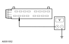
|
Yes GO to A6. No VERIFY CJB fuse 19 (7.5A) is OK. If OK, REPAIR circuit 1524 (DB). REPEAT the self-test, CLEAR the DTCs. DISCONNECT the battery ground cable. DISCONNECT the restraint system diagnostic tool from driver seat side air bag C315. CONNECT driver seat side air bag C315. REPOWER the SRS. REFER to Section 501-20B. | |||||||||||||||||||||||||||
| A6 CHECK CIRCUITS 983 (RD/LG), 982 (YE/LG), 918 (GY), 919 (GY/BK), 979 (RD/LB), 978 (YE/LB), 981 (RD/WH) AND 980 (YE/WH) FOR A SHORT TO POWER | ||||||||||||||||||||||||||||
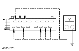
|
Yes GO to A7. No REPAIR the affected circuit for a short to power. REPEAT the self-test, CLEAR the DTCs. DISCONNECT the battery ground cable. DISCONNECT the restraint system diagnostic tool from driver seat side air bag C315. CONNECT driver seat side air bag C315. REPOWER the SRS. REFER to Section 501-20B. | |||||||||||||||||||||||||||
| A7 CHECK CIRCUITS 983 (RD/LG), 982 (YE/LG), 918 (GY), 919 (GY/BK), 979 (RD/LB), 978 (YE/LB), 981 (RD/WH) AND 980 (YE/WH) FOR AN OPEN CIRCUIT | ||||||||||||||||||||||||||||
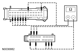
|
Yes INSTALL a new DDM. REFER to Section 419-10 for additional information. REPEAT the self-test, CLEAR the DTCs. DISCONNECT the battery ground cable. DISCONNECT the restraint system diagnostic tool from driver seat side air bag C315. CONNECT driver seat side air bag C315. REPOWER the SRS. REFER to Section 501-20B. No REPAIR the affected circuit for an open. REPEAT the self-test, CLEAR the DTCs. DISCONNECT the battery ground cable. DISCONNECT the restraint system diagnostic tool from driver seat side air bag C315. CONNECT driver seat side air bag C315. REPOWER the SRS. REFER to Section 501-20B. | |||||||||||||||||||||||||||
| A8 CHECK THE DRIVER SEAT OPERATION | ||||||||||||||||||||||||||||
|
Yes Go To Pinpoint Test D. No GO to A9. | |||||||||||||||||||||||||||
| A9 CHECK THE DSM OUTPUTS | ||||||||||||||||||||||||||||
|
Yes INSTALL a new DSM. REFER to Section 419-10 for additional information. REPEAT the self-test, CLEAR the DTCs. DISCONNECT the battery ground cable. DISCONNECT the restraint system diagnostic tool from driver seat side air bag C315. CONNECT driver seat side air bag C315. REPOWER the SRS. REFER to Section 501-20B. No If there is no seat movement, GO to A10 . If there is no front up/down seat movement, GO to A15 . If there is no rear up/down seat movement, GO to A20 . If there is no horizontal seat movement, GO to A25 . If there is no recline seat movement, GO to A31 . | |||||||||||||||||||||||||||
| A10 CHECK FOR VOLTAGE TO THE DSM | ||||||||||||||||||||||||||||
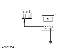
|
Yes GO to A11. No VERIFY BJB CB601 (20A) is OK. If OK, REPAIR circuit 490 (RD) for an open. REPEAT the self-test, CLEAR the DTCs. DISCONNECT the battery ground cable. DISCONNECT the restraint system diagnostic tool from driver seat side air bag C315. CONNECT driver seat side air bag C315. REPOWER the SRS. REFER to Section 501-20B. | |||||||||||||||||||||||||||
| A11 CHECK CIRCUIT 57 (BK) FOR AN OPEN | ||||||||||||||||||||||||||||
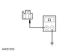
|
Yes GO to A12. No REPAIR circuit 57 (BK) for an open. REPEAT the self-test, CLEAR the DTCs. DISCONNECT the battery ground cable. DISCONNECT the restraint system diagnostic tool from driver seat side air bag C315. CONNECT driver seat side air bag C315. REPOWER the SRS. REFER to Section 501-20B. | |||||||||||||||||||||||||||
| A12 CHECK CIRCUITS 979 (RD/LB), 978 (YE/LB), 983 (RD/LG), 982 (YE/LG), 980 (YE/WH) AND 981 (RD/WH) FOR A SHORT TO GROUND | ||||||||||||||||||||||||||||
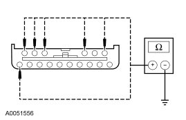
|
Yes LEAVE all seat motors disconnected and GO to A13 . No REPAIR the affected circuit for a short to ground. REPEAT the self-test, CLEAR the DTCs. DISCONNECT the battery ground cable. DISCONNECT the restraint system diagnostic tool from driver seat side air bag C315. CONNECT driver seat side air bag C315. REPOWER the SRS. REFER to Section 501-20B. | |||||||||||||||||||||||||||
| A13 CHECK CIRCUITS 919 (GY/BK) AND 918 (GY) FOR A SHORT TO GROUND | ||||||||||||||||||||||||||||
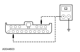
|
Yes GO to A14. No REPAIR the affected circuit for a short to ground. REPEAT the self-test, CLEAR the DTCs. DISCONNECT the battery ground cable. DISCONNECT the restraint system diagnostic tool from driver seat side air bag C315. CONNECT driver seat side air bag C315. REPOWER the SRS. REFER to Section 501-20B. | |||||||||||||||||||||||||||
| A14 CHECK THE RECLINE MOTOR FOR A SHORT TO GROUND | ||||||||||||||||||||||||||||
|
Yes INSTALL a new driver seat track motor and transmission assembly. REPEAT the self-test, CLEAR the DTCs. DISCONNECT the battery ground cable. DISCONNECT the restraint system diagnostic tool from driver seat side air bag C315. CONNECT driver seat side air bag C315. REPOWER the SRS. REFER to Section 501-20B. No INSTALL a new seat recline motor assembly. REFER to Seat Recliner — Power in this section. REPEAT the self-test, CLEAR the DTCs. DISCONNECT the battery ground cable. DISCONNECT the restraint system diagnostic tool from driver seat side air bag C315. CONNECT driver seat side air bag C315. REPOWER the SRS. REFER to Section 501-20B. | |||||||||||||||||||||||||||
| A15 CHECK THE FRONT SEAT HEIGHT MOTOR FOR CORRECT OPERATION | ||||||||||||||||||||||||||||
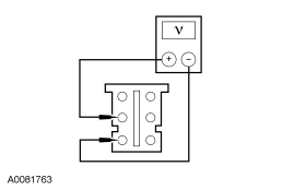
|
Yes GO to A16. No GO to A19. | |||||||||||||||||||||||||||
| A16 CHECK THE FRONT HEIGHT POSITION SENSOR CIRCUITS 443 (LG/RD), 446 (OG/WH) AND 447 (OG/RD) FOR A SHORT TO POWER | ||||||||||||||||||||||||||||
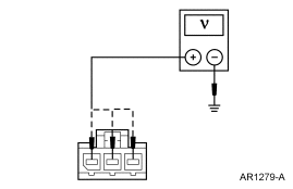
|
Yes GO to A17. No REPAIR the affected circuit for a short to power. REPEAT the self-test, CLEAR the DTCs. DISCONNECT the battery ground cable. DISCONNECT the restraint system diagnostic tool from driver seat side air bag C315. CONNECT driver seat side air bag C315. REPOWER the SRS. REFER to Section 501-20B. | |||||||||||||||||||||||||||
| A17 CHECK THE FRONT HEIGHT POSITION SENSOR CIRCUITS 443 (LG/RD), 446 (OG/WH) AND 447 (OG/RD) FOR A SHORT TO GROUND | ||||||||||||||||||||||||||||
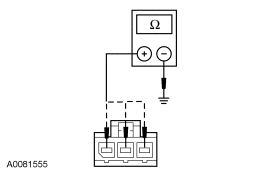
|
Yes GO to A18. No REPAIR the affected circuit for a short to ground. REPEAT the self-test, CLEAR the DTCs. DISCONNECT the battery ground cable. DISCONNECT the restraint system diagnostic tool from driver seat side air bag C315. CONNECT driver seat side air bag C315. REPOWER the SRS. REFER to Section 501-20B. | |||||||||||||||||||||||||||
| A18 CHECK THE FRONT HEIGHT POSITION SENSOR CIRCUITS 443 (LG/RD), 446 (OG/WH) AND 447 (OG/RD) FOR AN OPEN | ||||||||||||||||||||||||||||
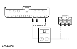
|
Yes INSTALL a new seat front height position sensor. REFER to Memory Seat Position Sensor in this section. GO to A33 . No REPAIR the affected circuit for an open. REPEAT the self-test, CLEAR the DTCs. DISCONNECT the battery ground cable. DISCONNECT the restraint system diagnostic tool from driver seat side air bag C315. CONNECT driver seat side air bag C315. REPOWER the SRS. REFER to Section 501-20B. | |||||||||||||||||||||||||||
| A19 CHECK CIRCUITS 979 (RD/LB) AND 978 (YE/LB) FOR AN OPEN | ||||||||||||||||||||||||||||
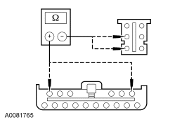
|
Yes INSTALL a new DSM. REFER to Section 419-10 for additional information. REPEAT the self-test, CLEAR the DTCs. DISCONNECT the battery ground cable. DISCONNECT the restraint system diagnostic tool from driver seat side air bag C315. CONNECT driver seat side air bag C315. REPOWER the SRS. REFER to Section 501-20B. No REPAIR the affected circuit for an open. REPEAT the self-test, CLEAR the DTCs. DISCONNECT the battery ground cable. DISCONNECT the restraint system diagnostic tool from driver seat side air bag C315. CONNECT driver seat side air bag C315. REPOWER the SRS. REFER to Section 501-20B. | |||||||||||||||||||||||||||
| A20 CHECK THE REAR HEIGHT MOTOR FOR CORRECT OPERATION | ||||||||||||||||||||||||||||
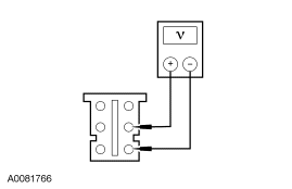
|
Yes GO to A21. No GO to A24. | |||||||||||||||||||||||||||
| A21 CHECK THE REAR HEIGHT POSITION SENSOR CIRCUITS 444 (LG/BK), 446 (OG/WH) AND 447 (OG/RD) FOR A SHORT TO POWER | ||||||||||||||||||||||||||||
|
Yes GO to A22. No REPAIR the affected circuit for a short to power. REPEAT the self-test, CLEAR the DTCs. DISCONNECT the battery ground cable. DISCONNECT the restraint system diagnostic tool from driver seat side air bag C315. CONNECT driver seat side air bag C315. REPOWER the SRS. REFER to Section 501-20B. | |||||||||||||||||||||||||||
| A22 CHECK THE REAR HEIGHT POSITION SENSOR CIRCUITS 444 (LG/BK), 446 (OG/WH) AND 447 (OG/RD) FOR A SHORT TO GROUND | ||||||||||||||||||||||||||||
|
Yes GO to A23. No REPAIR the affected circuit for a short to ground. REPEAT the self-test, CLEAR the DTCs. DISCONNECT the battery ground cable. DISCONNECT the restraint system diagnostic tool from driver seat side air bag C315. CONNECT driver seat side air bag C315. REPOWER the SRS. REFER to Section 501-20B. | |||||||||||||||||||||||||||
| A23 CHECK THE REAR HEIGHT POSITION SENSOR CIRCUITS 444 (LG/BK), 446 (OG/WH) AND 447 (OG/RD) FOR AN OPEN | ||||||||||||||||||||||||||||
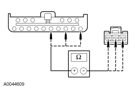
|
Yes INSTALL a new driver seat rear height position sensor. REFER to Memory Seat Position Sensor in this section. GO to A33 . No REPAIR the affected circuit for an open. REPEAT the self-test, CLEAR the DTCs. DISCONNECT the battery ground cable. DISCONNECT the restraint system diagnostic tool from driver seat side air bag C315. CONNECT driver seat side air bag C315. REPOWER the SRS. REFER to Section 501-20B. | |||||||||||||||||||||||||||
| A24 CHECK CIRCUITS 983 (RD/LG) AND 982 (YE/LG) FOR AN OPEN | ||||||||||||||||||||||||||||
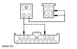
|
Yes INSTALL a new DSM. REFER to Section 419-10 for additional information. REPEAT the self-test, CLEAR the DTCs. DISCONNECT the battery ground cable. DISCONNECT the restraint system diagnostic tool from driver seat side air bag C315. CONNECT driver seat side air bag C315. REPOWER the SRS. REFER to Section 501-20B. No REPAIR the affected circuit for an open. REPEAT the self-test, CLEAR the DTCs. DISCONNECT the battery ground cable. DISCONNECT the restraint system diagnostic tool from driver seat side air bag C315. CONNECT driver seat side air bag C315. REPOWER the SRS. REFER to Section 501-20B. | |||||||||||||||||||||||||||
| A25 CHECK THE HORIZONTAL MOTOR FOR CORRECT OPERATION | ||||||||||||||||||||||||||||
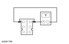
|
Yes GO to A26. No GO to A30. | |||||||||||||||||||||||||||
| A26 CHECK THE HORIZONTAL POSITION SENSOR CIRCUITS 442 (LG/OG), 446 (OG/WH) AND 447 (OG/RD) FOR A SHORT TO POWER | ||||||||||||||||||||||||||||
|
Yes GO to A27. No REPAIR the affected circuit for a short to power. REPEAT the self-test, CLEAR the DTCs. DISCONNECT the battery ground cable. DISCONNECT the restraint system diagnostic tool from driver seat side air bag C315. CONNECT driver seat side air bag C315. REPOWER the SRS. REFER to Section 501-20B. | |||||||||||||||||||||||||||
| A27 CHECK THE HORIZONTAL POSITION SENSOR CIRCUITS 442 (LG/OG), 446 (OG/WH) AND 447 (OG/RD) FOR A SHORT TO GROUND | ||||||||||||||||||||||||||||
|
Yes GO to A28. No REPAIR the affected circuit for a short to ground. REPEAT the self-test, CLEAR the DTCs. DISCONNECT the battery ground cable. DISCONNECT the restraint system diagnostic tool from driver seat side air bag C315. CONNECT driver seat side air bag C315. REPOWER the SRS. REFER to Section 501-20B. | |||||||||||||||||||||||||||
| A28 CHECK THE HORIZONTAL POSITION SENSOR CIRCUITS 442 (LG/OG), 446 (OG/WH) AND 447 (OG/RD) FOR AN OPEN | ||||||||||||||||||||||||||||
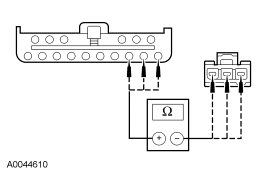
|
Yes GO to A29. No REPAIR the affected circuit for an open. REPEAT the self-test, CLEAR the DTCs. DISCONNECT the battery ground cable. DISCONNECT the restraint system diagnostic tool from driver seat side air bag C315. CONNECT driver seat side air bag C315. REPOWER the SRS. REFER to Section 501-20B. | |||||||||||||||||||||||||||
| A29 CHECK THE SEAT TRACK OPERATION | ||||||||||||||||||||||||||||
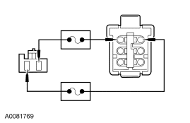
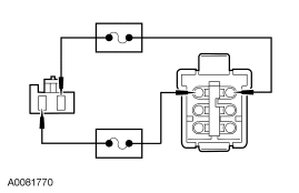
|
Yes INSTALL a new horizontal memory seat position sensor. REFER to Memory Seat Position Sensor in this section. REPEAT the self-test, CLEAR the DTCs. DISCONNECT the battery ground cable. DISCONNECT the restraint system diagnostic tool from driver seat side air bag C315. CONNECT driver seat side air bag C315. REPOWER the SRS. REFER to Section 501-20B. No INSTALL a new driver seat track motor and transmission assembly. REPEAT the self-test, CLEAR the DTCs. DISCONNECT the battery ground cable. DISCONNECT the restraint system diagnostic tool from driver seat side air bag C315. CONNECT driver seat side air bag C315. REPOWER the SRS. REFER to Section 501-20B. | |||||||||||||||||||||||||||
| A30 CHECK CIRCUITS 980 (YE/WH) AND 981 (RD/WH) FOR AN OPEN | ||||||||||||||||||||||||||||
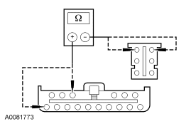
|
Yes INSTALL a new DSM. REFER to Section 419-10 for additional information. REPEAT the self-test, CLEAR the DTCs. DISCONNECT the battery ground cable. DISCONNECT the restraint system diagnostic tool from driver seat side air bag C315. CONNECT driver seat side air bag C315. REPOWER the SRS. REFER to Section 501-20B. No REPAIR the affected circuit for an open. REPEAT the self-test, CLEAR the DTCs. DISCONNECT the battery ground cable. DISCONNECT the restraint system diagnostic tool from driver seat side air bag C315. CONNECT driver seat side air bag C315. REPOWER the SRS. REFER to Section 501-20B. | |||||||||||||||||||||||||||
| A31 CHECK THE POWER SEAT RECLINE MOTOR FOR CORRECT OPERATION | ||||||||||||||||||||||||||||
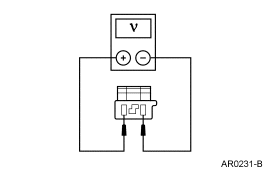
|
Yes INSTALL a new power seat recline motor. REFER to Seat Recliner — Power in this section. REPEAT the self-test, CLEAR the DTCs. DISCONNECT the battery ground cable. DISCONNECT the restraint system diagnostic tool from driver seat side air bag C315. CONNECT driver seat side air bag C315. REPOWER the SRS. REFER to Section 501-20B. No GO to A32. | |||||||||||||||||||||||||||
| A32 CHECK CIRCUITS 919 (GY/BK) AND 918 (GY) FOR AN OPEN | ||||||||||||||||||||||||||||
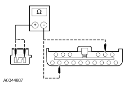
|
Yes INSTALL a new DSM. REFER to Section 419-10 for additional information. REPEAT the self-test, CLEAR the DTCs. DISCONNECT the battery ground cable. DISCONNECT the restraint system diagnostic tool from driver seat side air bag C315. CONNECT driver seat side air bag C315. REPOWER the SRS. REFER to Section 501-20B. No REPAIR the affected circuit for an open. REPEAT the self-test, CLEAR the DTCs. DISCONNECT the battery ground cable. DISCONNECT the restraint system diagnostic tool from driver seat side air bag C315. CONNECT driver seat side air bag C315. REPOWER the SRS. REFER to Section 501-20B. | |||||||||||||||||||||||||||
| A33 CHECK THE SEAT FOR NORMAL OPERATION | ||||||||||||||||||||||||||||
|
Yes The system is operating correctly at this time. REPEAT the self-test, CLEAR the DTCs. DISCONNECT the battery ground cable. DISCONNECT the restraint system diagnostic tool from driver seat side air bag C315. CONNECT driver seat side air bag C315. REPOWER the SRS. REFER to Section 501-20B. No INSTALL a new driver seat track motor and transmission assembly. REPEAT the self-test, CLEAR the DTCs. DISCONNECT the battery ground cable. DISCONNECT the restraint system diagnostic tool from driver seat side air bag C315. CONNECT driver seat side air bag C315. REPOWER the SRS. REFER to Section 501-20B. |
Pinpoint Test B: The Power Seat Is Inoperative — Driver
Refer to Wiring Diagrams Cell 120, Power Seats for schematic and connector information.
Normal Operation
The seat control switch is powered by battery voltage to circuit 490 (RD) and is supplied ground on circuit 57 (BK). The seat control switch applies battery power and ground directly to the appropriate seat track motor or recliner motor, to move the seat.
Possible Causes
An inoperative driver power seat can be caused by:
- a faulty circuit breaker.
- wiring, terminals or connectors.
- a faulty seat control switch.
- a faulty seat track.
PINPOINT TEST B: THE POWER SEAT IS INOPERATIVE — DRIVER
| Test Step | Result / Action to Take |
|---|---|
| B1 CHECK FOR SWITCH OUTPUT | |
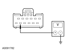
|
Yes GO to B2. No VERIFY BJB circuit breaker 601 (20A) is OK. If OK, REPAIR driver circuit 490 (RD). TEST the system for normal operation. DISCONNECT the battery ground cable. DISCONNECT the restraint system diagnostic tool from driver seat side air bag C315. CONNECT driver seat side air bag C315. REPOWER the SRS. REFER to Section 501-20B. |
| B2 CHECK THE SWITCH GROUND | |
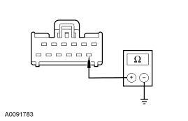
|
Yes INSTALL a new seat control switch. TEST the system for normal operation. DISCONNECT the battery ground cable. DISCONNECT the restraint system diagnostic tool from driver seat side air bag C315. CONNECT driver seat side air bag C315. REPOWER the SRS. REFER to Section 501-20B. No REPAIR circuit 57 (BK) for an open. TEST the system for normal operation. DISCONNECT the battery ground cable. DISCONNECT the restraint system diagnostic tool from driver seat side air bag C315. CONNECT driver seat side air bag C315. REPOWER the SRS. REFER to Section 501-20B. |
Pinpoint Test C: The Power Seat Is Inoperative — Passenger
Refer to Wiring Diagrams Cell 120, Power Seats for schematic and connector information.
Normal Operation
The seat control switch is powered by battery voltage to circuit 490 (RD) and is supplied ground on circuit 57 (BK). The seat control switch applies battery power and ground directly to the appropriate seat track motor or recliner motor, to move the seat.
Possible Causes
An inoperative passenger power seat can be caused by:
- a faulty circuit breaker.
- wiring, terminals or connectors.
- a faulty seat control switch.
- a faulty seat track.
PINPOINT TEST C: THE POWER SEAT IS INOPERATIVE — PASSENGER
| Test Step | Result / Action to Take |
|---|---|
| C1 CHECK FOR SWITCH OUTPUT | |
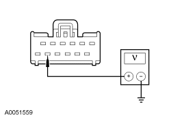
|
Yes GO to C2. No VERIFY BJB circuit breaker 601 (20A) is OK. If OK, REPAIR passenger circuit 490 (RD). TEST the system for normal operation. DISCONNECT the battery ground cable. DISCONNECT the restraint system diagnostic tool from passenger seat side air bag C316. CONNECT passenger seat side air bag C316. REPOWER the SRS. REFER to Section 501-20B. |
| C2 CHECK THE SWITCH GROUND | |
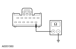
|
Yes INSTALL a new seat control switch. TEST the system for normal operation. No REPAIR circuit 57 (BK). TEST the system for normal operation. DISCONNECT the battery ground cable. DISCONNECT the restraint system diagnostic tool from passenger seat side air bag C316. CONNECT passenger seat side air bag C316. REPOWER the SRS. REFER to Section 501-20B. |
Pinpoint Test D: The Memory Seat Does Not Operate Correctly — Motors Operate In One Second Intervals Or Memory Seat Recall Not Functioning Correctly
Refer to Wiring Diagrams Cell 123, Memory Seats for schematic and connector information.
Refer to Wiring Diagrams Cell 57, Driver Door Module for schematic and connector information.
Normal Operation
The memory seat recall feature should operate the seat track and recliner motors smoothly to their preset positions when a stored driver 1 or 2 memory recall selection is activated. The recall can be activated by either the memory seat position switch or the remote keyless entry transmitter (key FOB). When activated, the DSM will apply power to each of the seat motors as needed to move the seat to the preset positions. The DSM monitors input signals from each of the memory seat position sensors to calculate each of the motors positions and will remove power from each motor once the calibrated position is attained. A missing sensor signal or faulty motor may cause the seat to operate in a pulsating manner (one-second intervals) or to become inoperative.
Possible Causes
An inoperative memory recall feature or a memory seat motor that cycles in one-second intervals may be caused by:
- wiring, terminals or connectors.
- a faulty memory seat position sensor.
- a faulty memory seat position switch.
- a faulty seat track motor.
- a faulty DSM.
PINPOINT TEST D: THE MEMORY SEAT DOES NOT OPERATE CORRECTLY — MOTORS OPERATE IN ONE SECOND INTERVALS OR MEMORY SEAT RECALL NOT FUNCTIONING CORRECTLY
NOTE: Make sure the battery is in good condition and fully charged before carrying out diagnostics.
| Test Step | Result / Action to Take | ||||||||||||
|---|---|---|---|---|---|---|---|---|---|---|---|---|---|
| D1 CHECK THE POWER SEAT OPERATION | |||||||||||||
|
Yes GO to D2. No GO to Symptom Chart to diagnose the inoperative seat function. | ||||||||||||
| D2 CHECK FOR DRIVER DOOR MODULE (DDM) DTCS | |||||||||||||
|
Yes For DTC(s) B1703, B1707, B1711, B1715, B1719, B1723, B1727 or B1731, Go To Pinpoint Test A. For all others, REFER to the Diagnostic Trouble Code (DTC) Index in Section 419-10 to diagnose the DDM concern. No GO to D3. | ||||||||||||
| D3 CHECK FOR DRIVER SEAT MODULE (DSM) DTCS | |||||||||||||
|
Yes If DTCs B1663 and B1957 were retrieved, GO to D5 . If DTCs B1663 and B1954 were retrieved, GO to D6 . If DTCs B1664 and B1953 were retrieved, GO to D8 . If DTCs B1664 and B1950 were retrieved, GO to D9 . If DTCs B1665 and B1965 were retrieved, GO to D11 . If DTCs B1665 and B1962 were retrieved, GO to D12 . If DTCs B1666 and B1961 were retrieved, GO to D14 . If DTCs B1666 and B1958 were retrieved, GO to D15 . If DTCs B1663, B1664, B1665 and B1966 are all retrieved, GO to D4 . If DTCs B1663, B1664, B1665, B1666, B1667, B1668, B1669 and B1670 are all retrieved, GO to D17 . If DTC B1676 is retrieved, Go To Pinpoint Test W. For all others, REFER to the Diagnostic Trouble Code (DTC) Index in Section 419-10 to diagnose the DSM concern. No GO to D4. | ||||||||||||
| D4 CHECK THE DSM FOR THE CORRECT OUTPUTS | |||||||||||||
|
Yes INSTALL a new DSM. REFER to Section 419-10 for additional information. REPEAT the self-test, CLEAR the DTCs. DISCONNECT the battery ground cable. DISCONNECT the restraint system diagnostic tool from driver seat side air bag C315. CONNECT driver seat side air bag C315. REPOWER the SRS. REFER to Section 501-20B. No If all the driver seat motors do not operate correctly, GO to D17 . If the driver seat front height motor is not operating correctly, GO to D5 . If the driver seat rear height motor is not operating correctly, GO to D8 . If the driver seat horizontal motor is not operating correctly, GO to D11 . If the driver seat recline motor is not operating correctly, GO to D14 . | ||||||||||||
| D5 CHECK THE FRONT HEIGHT POSITION SENSOR CIRCUITS 443 (LG/RD), 446 (OG/WH) AND 447 (OG/RD) FOR A SHORT TO GROUND | |||||||||||||
|
Yes GO to D6. No REPAIR the affected circuit for a short to ground. REPEAT the self-test, CLEAR the DTCs. DISCONNECT the battery ground cable. DISCONNECT the restraint system diagnostic tool from driver seat side air bag C315. CONNECT driver seat side air bag C315. REPOWER the SRS. REFER to Section 501-20B. | ||||||||||||
| D6 CHECK CIRCUITS 443 (LG/RD), 446 (OG/WH) AND 447 (OG/RD) FOR AN OPEN | |||||||||||||
|
Yes GO to D7. No REPAIR the affected circuit for an open. REPEAT the self-test, CLEAR the DTCs. DISCONNECT the battery ground cable. DISCONNECT the restraint system diagnostic tool from driver seat side air bag C315. CONNECT driver seat side air bag C315. REPOWER the SRS. REFER to Section 501-20B. | ||||||||||||
| D7 CHECK CIRCUITS 443 (LG/RD), 446 (OG/WH) AND 447 (OG/RD) FOR A SHORT TO POWER | |||||||||||||
|
Yes REPAIR the affected circuit for a short to power. REPEAT the self-test, CLEAR the DTCs. DISCONNECT the battery ground cable. DISCONNECT the restraint system diagnostic tool from driver seat side air bag C315. CONNECT driver seat side air bag C315. REPOWER the SRS. REFER to Section 501-20B. No GO to D21. | ||||||||||||
| D8 CHECK THE REAR HEIGHT POSITION SENSOR CIRCUITS 444 (LG/BK), 446 (OG/WH) AND 447 (OG/RD) FOR A SHORT TO GROUND | |||||||||||||
|
Yes GO to D9. No REPAIR the affected circuit for a short to ground. REPEAT the self-test, CLEAR the DTCs. DISCONNECT the battery ground cable. DISCONNECT the restraint system diagnostic tool from driver seat side air bag C315. CONNECT driver seat side air bag C315. REPOWER the SRS. REFER to Section 501-20B. | ||||||||||||
| D9 CHECK CIRCUITS 444 (LG/BK), 446 (OG/WH) AND 447 (OG/RD) FOR AN OPEN | |||||||||||||
|
Yes GO to D10. No REPAIR the affected circuit for an open. REPEAT the self-test, CLEAR the DTCs. DISCONNECT the battery ground cable. DISCONNECT the restraint system diagnostic tool from driver seat side air bag C315. CONNECT driver seat side air bag C315. REPOWER the SRS. REFER to Section 501-20B. | ||||||||||||
| D10 CHECK CIRCUITS 444 (LG/BK), 446 (OG/WH) AND 447 (OG/RD) FOR A SHORT TO POWER | |||||||||||||
|
Yes REPAIR the affected circuit for a short to power. REPEAT the self-test, CLEAR the DTCs. DISCONNECT the battery ground cable. DISCONNECT the restraint system diagnostic tool from driver seat side air bag C315. CONNECT driver seat side air bag C315. REPOWER the SRS. REFER to Section 501-20B. No GO to D23. | ||||||||||||
| D11 CHECK THE HORIZONTAL POSITION SENSOR CIRCUITS 442 (LG/OG), 446 (OG/WH) AND 447 (OG/RD) FOR A SHORT TO GROUND | |||||||||||||
|
Yes GO to D12. No REPAIR the affected circuit for a short to ground. REPEAT the self-test, CLEAR the DTCs. DISCONNECT the battery ground cable. DISCONNECT the restraint system diagnostic tool from driver seat side air bag C315. CONNECT driver seat side air bag C315. REPOWER the SRS. REFER to Section 501-20B. | ||||||||||||
| D12 CHECK CIRCUITS 442 (LG/OG), 446 (OG/WH) AND 447 (OG/RD) FOR AN OPEN | |||||||||||||
|
Yes GO to D13. No REPAIR the affected circuit for an open. REPEAT the self-test, CLEAR the DTCs. DISCONNECT the battery ground cable. DISCONNECT the restraint system diagnostic tool from driver seat side air bag C315. CONNECT driver seat side air bag C315. REPOWER the SRS. REFER to Section 501-20B. | ||||||||||||
| D13 CHECK CIRCUITS 442 (LG/OG), 446 (OG/WH) AND 447 (OG/RD) FOR A SHORT TO POWER | |||||||||||||
|
Yes REPAIR the affected circuit for a short to power. REPEAT the self-test, CLEAR the DTCs. DISCONNECT the battery ground cable. DISCONNECT the restraint system diagnostic tool from driver seat side air bag C315. CONNECT driver seat side air bag C315. REPOWER the SRS. REFER to Section 501-20B. No GO to D25. | ||||||||||||
| D14 CHECK THE RECLINE POSITION SENSOR CIRCUITS 445 (OG/LB), 446 (OG/WH) AND 447 (OG/RD) FOR A SHORT TO GROUND | |||||||||||||
|
Yes GO to D15. No REPAIR the affected circuit for a short to ground. REPEAT the self-test, CLEAR the DTCs. DISCONNECT the battery ground cable. DISCONNECT the restraint system diagnostic tool from driver seat side air bag C315. CONNECT driver seat side air bag C315. REPOWER the SRS. REFER to Section 501-20B. | ||||||||||||
| D15 CHECK CIRCUITS 445 (OG/LB), 446 (OG/WH) AND 447 (OG/RD) FOR AN OPEN CIRCUIT | |||||||||||||
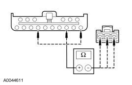
|
Yes GO to D16. No REPAIR the affected circuit for an open. REPEAT the self-test, CLEAR the DTCs. DISCONNECT the battery ground cable. DISCONNECT the restraint system diagnostic tool from driver seat side air bag C315. CONNECT driver seat side air bag C315. REPOWER the SRS. REFER to Section 501-20B. | ||||||||||||
| D16 CHECK CIRCUITS 445 (OG/LB), 446 (OG/WH) AND 447 (OG/RD) FOR A SHORT TO POWER | |||||||||||||
|
Yes REPAIR the affected circuit for a short to power. REPEAT the self-test, CLEAR the DTCs. DISCONNECT the battery ground cable. DISCONNECT the restraint system diagnostic tool from driver seat side air bag C315. CONNECT driver seat side air bag C315. REPOWER the SRS. REFER to Section 501-20B. No GO to D27. | ||||||||||||
| D17 CHECK CIRCUIT 446 (OG/WH) FOR AN OPEN | |||||||||||||
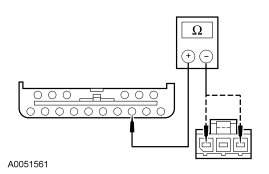
|
Yes GO to D18. No REPAIR circuit 446 (OG/WH) for an open. REPEAT the self-test, CLEAR the DTCs. DISCONNECT the battery ground cable. DISCONNECT the restraint system diagnostic tool from driver seat side air bag C315. CONNECT driver seat side air bag C315. REPOWER the SRS. REFER to Section 501-20B. | ||||||||||||
| D18 CHECK CIRCUIT 447 (OG/RD) FOR AN OPEN | |||||||||||||
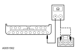
|
Yes GO to D19. No REPAIR circuit 447 (OG/RD) for an open. REPEAT the self-test, CLEAR the DTCs. DISCONNECT the battery ground cable. DISCONNECT the restraint system diagnostic tool from driver seat side air bag C315. CONNECT driver seat side air bag C315. REPOWER the SRS. REFER to Section 501-20B. | ||||||||||||
| D19 CHECK CIRCUIT 446 (OG/WH) FOR A SHORT TO GROUND | |||||||||||||
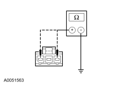
|
Yes GO to D20. No REPAIR circuit 446 (OG/WH) for a short to ground. REPEAT the self-test, CLEAR the DTCs. DISCONNECT the battery ground cable. DISCONNECT the restraint system diagnostic tool from driver seat side air bag C315. CONNECT driver seat side air bag C315. REPOWER the SRS. REFER to Section 501-20B. | ||||||||||||
| D20 CHECK CIRCUIT 446 (OG/WH) FOR A SHORT TO POWER | |||||||||||||
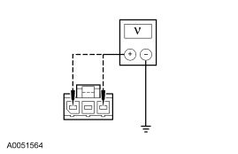
|
Yes REPAIR circuit 446 (OG/WH) for a short to power. REPEAT the self-test, CLEAR the DTCs. DISCONNECT the battery ground cable. DISCONNECT the restraint system diagnostic tool from driver seat side air bag C315. CONNECT driver seat side air bag C315. REPOWER the SRS. REFER to Section 501-20B. No GO to D29. | ||||||||||||
| D21 CHECK CIRCUITS 446 (OG/WH) AND 443 (LG/RD) FOR POWER | |||||||||||||
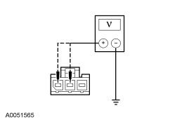
|
Yes GO to D22. No INSTALL a new DSM. REFER to Section 419-10 for additional information. REPEAT the self-test, CLEAR the DTCs. DISCONNECT the battery ground cable. DISCONNECT the restraint system diagnostic tool from driver seat side air bag C315. CONNECT driver seat side air bag C315. REPOWER the SRS. REFER to Section 501-20B. | ||||||||||||
| D22 CHECK CIRCUIT 447 (OG/RD) FOR GROUND | |||||||||||||
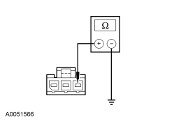
|
Yes INSTALL a new driver seat front height position sensor. REFER to Memory Seat Position Sensor in this section. REPEAT the self-test, CLEAR the DTCs. DISCONNECT the battery ground cable. DISCONNECT the restraint system diagnostic tool from driver seat side air bag C315. CONNECT driver seat side air bag C315. REPOWER the SRS. REFER to Section 501-20B. No INSTALL a new DSM. REFER to Section 419-10 for additional information. REPEAT the self-test, CLEAR the DTCs. DISCONNECT the battery ground cable. DISCONNECT the restraint system diagnostic tool from driver seat side air bag C315. CONNECT driver seat side air bag C315. REPOWER the SRS. REFER to Section 501-20B. | ||||||||||||
| D23 CHECK CIRCUITS 446 (OG/WH) AND 444 (LG/BK) FOR POWER | |||||||||||||
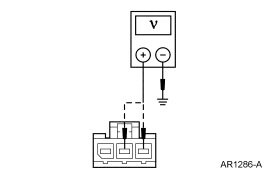
|
Yes GO to D24. No INSTALL a new DSM. REFER to Section 419-10 for additional information. REPEAT the self-test, CLEAR the DTCs. DISCONNECT the battery ground cable. DISCONNECT the restraint system diagnostic tool from driver seat side air bag C315. CONNECT driver seat side air bag C315. REPOWER the SRS. REFER to Section 501-20B. | ||||||||||||
| D24 CHECK REAR HEIGHT POSITION SENSOR CIRCUIT 447 (OG/RD) FOR GROUND | |||||||||||||
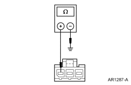
|
Yes INSTALL a new rear height position sensor. REFER to Memory Seat Position Sensor in this section. REPEAT the self-test, CLEAR the DTCs. DISCONNECT the battery ground cable. DISCONNECT the restraint system diagnostic tool from driver seat side air bag C315. CONNECT driver seat side air bag C315. REPOWER the SRS. REFER to Section 501-20B. No INSTALL a new DSM. REFER to Section 419-10. REPEAT the self-test, CLEAR the DTCs. DISCONNECT the battery ground cable. DISCONNECT the restraint system diagnostic tool from driver seat side air bag C315. CONNECT driver seat side air bag C315. REPOWER the SRS. REFER to Section 501-20B. | ||||||||||||
| D25 CHECK CIRCUITS 446 (OG/WH) AND 442 (LG/OG) FOR POWER | |||||||||||||
|
Yes GO to D26. No INSTALL a new DSM. REFER to Section 419-10 for additional information. REPEAT the self-test, CLEAR the DTCs. DISCONNECT the battery ground cable. DISCONNECT the restraint system diagnostic tool from driver seat side air bag C315. CONNECT driver seat side air bag C315. REPOWER the SRS. REFER to Section 501-20B. | ||||||||||||
| D26 CHECK HORIZONTAL POSITION SENSOR CIRCUIT 447 (OG/RD) FOR GROUND | |||||||||||||
|
Yes INSTALL a new horizontal position sensor. REFER to Memory Seat Position Sensor in this section. REPEAT the self-test, CLEAR the DTCs. DISCONNECT the battery ground cable. DISCONNECT the restraint system diagnostic tool from driver seat side air bag C315. CONNECT driver seat side air bag C315. REPOWER the SRS. REFER to Section 501-20B. No INSTALL a new DSM. REFER to Section 419-10 for additional information. REPEAT the self-test, CLEAR the DTCs. DISCONNECT the battery ground cable. DISCONNECT the restraint system diagnostic tool from driver seat side air bag C315. CONNECT driver seat side air bag C315. REPOWER the SRS. REFER to Section 501-20B. | ||||||||||||
| D27 CHECK CIRCUITS 446 (OG/WH) AND 445 (OG/LB) FOR POWER | |||||||||||||
|
Yes GO to D28. No INSTALL a new DSM. REFER to Section 419-10 for additional information. REPEAT the self-test, CLEAR the DTCs. DISCONNECT the battery ground cable. DISCONNECT the restraint system diagnostic tool from driver seat side air bag C315. CONNECT driver seat side air bag C315. REPOWER the SRS. REFER to Section 501-20B. | ||||||||||||
| D28 CHECK RECLINE POSITION SENSOR CIRCUIT 447 (OG/RD) FOR GROUND | |||||||||||||
|
Yes INSTALL a new power seat recliner. REFER to Seat Recliner — Power in this section. REPEAT the self-test, CLEAR the DTCs. DISCONNECT the battery ground cable. DISCONNECT the restraint system diagnostic tool from driver seat side air bag C315. CONNECT driver seat side air bag C315. REPOWER the SRS. REFER to Section 501-20B. No INSTALL a new DSM. REFER to Section 419-10 for additional information. REPEAT the self-test, CLEAR the DTCs. DISCONNECT the battery ground cable. DISCONNECT the restraint system diagnostic tool from driver seat side air bag C315. CONNECT driver seat side air bag C315. REPOWER the SRS. REFER to Section 501-20B. | ||||||||||||
| D29 CHECK FOR COMMON DTCS | |||||||||||||
|
Yes REFER to Section 501-09 to diagnose multiple DTCs B1667, B1668, B1669 and B1670 or Section 206-06 to diagnose DTC B1987. If still unable to diagnosis concern, INSTALL a new DSM. REFER to Section 419-10 for additional information. REPEAT the self-test, CLEAR the DTCs. DISCONNECT the battery ground cable. DISCONNECT the restraint system diagnostic tool from driver seat side air bag C315. CONNECT driver seat side air bag C315. REPOWER the SRS. REFER to Section 501-20B. No INSTALL a new DSM. REFER to Section 419-10 for additional information. REPEAT the self-test, CLEAR the DTCs. DISCONNECT the battery ground cable. DISCONNECT the restraint system diagnostic tool from driver seat side air bag C315. CONNECT driver seat side air bag C315. REPOWER the SRS. REFER to Section 501-20B. |
Pinpoint Test E: The Power Seat Does Not Move Horizontally/Vertically/Recline — Driver
Refer to Wiring Diagrams Cell 120, Power Seats for schematic and connector information.
Normal Operation
The driver seat control switch is powered by battery voltage on circuit 490 (RD) and is supplied ground on circuit 57 (BK). When pressed, the seat control switch supplies that voltage and ground to the appropriate power seat track motor or recliner motor to move the seat or backrest. When pressed in the opposite direction, the seat control switch reverses the polarity to that same power seat track motor, which moves the seat or backrest in the opposite direction. There are 3 power seat track motors that combine to move the seat horizontally (FORWARD/REVERSE) and vertically (front UP/DOWN and rear UP/DOWN).
Possible Causes
A driver power seat that does not move horizontally and/or vertically can be caused by:
- wiring, terminals or connectors.
- a faulty seat control switch.
- a faulty power recliner assembly.
- a faulty seat track motor.
PINPOINT TEST E: THE POWER SEAT DOES NOT MOVE HORIZONTALLY/VERTICALLY/RECLINE — DRIVER
| Test Step | Result / Action to Take | |||||||||||||||||||||||||||
|---|---|---|---|---|---|---|---|---|---|---|---|---|---|---|---|---|---|---|---|---|---|---|---|---|---|---|---|---|
| E1 CHECK THE MOTOR OPERATION | ||||||||||||||||||||||||||||
|
Yes INSTALL a new front seat track motor and transmission assembly or the recliner assembly. TEST the system for normal operation. DISCONNECT the battery ground cable. DISCONNECT the restraint system diagnostic tool from driver seat side air bag C315. CONNECT driver seat side air bag C315. REPOWER the SRS. REFER to Section 501-20B. No GO to E2. | |||||||||||||||||||||||||||
| E2 CHECK THE MOTOR CIRCUITS FOR A SHORT TO POWER | ||||||||||||||||||||||||||||
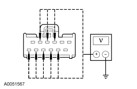
|
Yes REPAIR the affected circuit for a short to power. TEST the system for normal operation. DISCONNECT the battery ground cable. DISCONNECT the restraint system diagnostic tool from driver seat side air bag C315. CONNECT driver seat side air bag C315. REPOWER the SRS. REFER to Section 501-20B. No GO to E3. | |||||||||||||||||||||||||||
| E3 CHECK FOR A SHORT TO GROUND | ||||||||||||||||||||||||||||
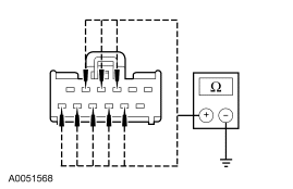
|
Yes GO to E4. No REPAIR the affected circuit for a short to ground. TEST the system for normal operation. DISCONNECT the battery ground cable. DISCONNECT the restraint system diagnostic tool from driver seat side air bag C315. CONNECT driver seat side air bag C315. REPOWER the SRS. REFER to Section 501-20B. | |||||||||||||||||||||||||||
| E4 CHECK FOR AN OPEN CIRCUIT | ||||||||||||||||||||||||||||
|
Yes INSTALL a new driver seat control switch. TEST the system for normal operation. DISCONNECT the battery ground cable. DISCONNECT the restraint system diagnostic tool from driver seat side air bag C315. CONNECT driver seat side air bag C315. REPOWER the SRS. REFER to Section 501-20B. No REPAIR the affected circuit for an open. TEST the system for normal operation. DISCONNECT the battery ground cable. DISCONNECT the restraint system diagnostic tool from driver seat side air bag C315. CONNECT driver seat side air bag C315. REPOWER the SRS. REFER to Section 501-20B. |
Pinpoint Test F: The Power Seat Does Not Move Horizontally/Vertically/Recline — Passenger
Refer to Wiring Diagrams Cell 120, Power Seats for schematic and connector information.
Normal Operation
The passenger seat control switch is powered by battery voltage on circuit 490 (RD) and is supplied ground on circuit 57 (BK). When pressed, the seat control switch supplies that voltage and ground to the appropriate passenger power seat track or recliner motor circuits to move the seat or backrest. When pressed in the opposite direction, the seat control switch reverses the polarity to that same power seat track or recliner motor, which moves the seat or backrest in the opposite direction. There are 3 power seat track motors that combine to move the seat horizontally (FORWARD/REVERSE) and vertically (front UP/DOWN and rear UP/DOWN).
Possible Causes
A passenger power seat that does not move horizontally and/or vertically can be caused by:
- wiring, terminals or connectors.
- a faulty seat control switch.
- a faulty power recliner assembly.
- a faulty seat track motor.
PINPOINT TEST F: THE POWER SEAT DOES NOT MOVE HORIZONTALLY/VERTICALLY/RECLINE — PASSENGER
| Test Step | Result / Action to Take | |||||||||||||||||||||||||||
|---|---|---|---|---|---|---|---|---|---|---|---|---|---|---|---|---|---|---|---|---|---|---|---|---|---|---|---|---|
| F1 CHECK THE MOTOR OPERATION | ||||||||||||||||||||||||||||
|
Yes INSTALL a new front seat track motor and transmission assembly or the recliner assembly. TEST the system for normal operation. DISCONNECT the battery ground cable. DISCONNECT the restraint system diagnostic tool from passenger seat side air bag C316. CONNECT passenger seat side air bag C316. REPOWER the SRS. REFER to Section 501-20B. No GO to F2. | |||||||||||||||||||||||||||
| F2 CHECK THE MOTOR CIRCUITS FOR A SHORT TO POWER | ||||||||||||||||||||||||||||
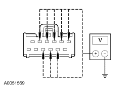
|
Yes REPAIR the affected circuit for a short to power. TEST the system for normal operation. DISCONNECT the battery ground cable. DISCONNECT the restraint system diagnostic tool from passenger seat side air bag C316. CONNECT passenger seat side air bag C316. REPOWER the SRS. REFER to Section 501-20B. No GO to F3. | |||||||||||||||||||||||||||
| F3 CHECK FOR A SHORT TO GROUND | ||||||||||||||||||||||||||||
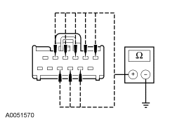
|
Yes GO to F4. No REPAIR the affected circuit for a short to ground. TEST the system for normal operation. DISCONNECT the battery ground cable. DISCONNECT the restraint system diagnostic tool from passenger seat side air bag C316. CONNECT passenger seat side air bag C316. REPOWER the SRS. REFER to Section 501-20B. | |||||||||||||||||||||||||||
| F4 CHECK FOR AN OPEN CIRCUIT | ||||||||||||||||||||||||||||
|
Yes INSTALL a new passenger seat control switch. TEST the system for normal operation. DISCONNECT the battery ground cable. DISCONNECT the restraint system diagnostic tool from passenger seat side air bag C316. CONNECT passenger seat side air bag C316. REPOWER the SRS. REFER to Section 501-20B. No REPAIR the affected circuit for an open. TEST the system for normal operation. DISCONNECT the battery ground cable. DISCONNECT the restraint system diagnostic tool from passenger seat side air bag C316. CONNECT passenger seat side air bag C316. REPOWER the SRS. REFER to Section 501-20B. |
Pinpoint Test G: The Memory Seat Does Not Operate Correctly — Seat Recall Feature Is Inoperative, Does Not Operate Correctly/The Memory Seat Does Not Move Horizontally/Vertically/Recline
Refer to Wiring Diagrams Cell 123, Memory Seats for schematic and connector information.
Refer to Wiring Diagrams Cell 57, Driver Door Module for schematic and connector information.
Refer to Wiring Diagrams Cell 149, Component Testing for schematic and connector information.
Normal Operation
A 3-lead sensor is attached to each motor on the memory seat track and recliner assembly. The sensor circuits are connected to the driver seat module (DSM) which supplies the sensor power and receives the sensor signals. The DSM receives data from the memory seat position sensors to monitor the positions of the seat track and recliner motors. This motor position data is stored when the DSM receives a SET switch input signal and recalled when it receives a RECALL switch input signal. The driver door module (DDM) is directly connected to the memory SET/RECALL switch and transmits the switch signal data to the DSM using the SCP communication bus. The DSM also receives memory recall signals from the remote transmitter over the SCP communication bus transmitted by the lighting control module (LCM).
Possible Causes
A memory seat that does not move horizontally, vertically or does not recline can be caused by:
- wiring, terminals or connectors.
- a faulty memory set switch.
- a faulty power seat track motor position sensor.
- a faulty DSM.
PINPOINT TEST G: THE MEMORY SEAT DOES NOT OPERATE CORRECTLY — SEAT RECALL FEATURE IS INOPERATIVE, DOES NOT OPERATE CORRECTLY/THE MEMORY SEAT DOES NOT MOVE HORIZONTALLY/VERTICALLY/RECLINE
NOTE: Make sure the battery is in good condition and fully charged before carrying out diagnostics.
| Test Step | Result / Action to Take | ||||||||
|---|---|---|---|---|---|---|---|---|---|
| G1 CHECK FOR DRIVER DOOR MODULE (DDM) DTCS | |||||||||
|
Yes For DTC B1703, B1707, B1711, B1715, B1719, B1723, B1727 or B1731, Go To Pinpoint Test A. For all others, REFER to the Diagnostic Trouble Code (DTC) Index in Section 419-10 to diagnose the DDM concern. No GO to G2. | ||||||||
| G2 CHECK THE POWER SEAT OPERATION | |||||||||
|
Yes GO to G3. No GO to Symptom Chart to diagnose the inoperative seat function. | ||||||||
| G3 CHECK THE MEMORY RECALL OPERATION | |||||||||
|
Yes GO to G4. No GO to G5. | ||||||||
| G4 CHECK THE MEMORY RECALL OPERATION FROM THE REMOTE KEYLESS ENTRY TRANSMITTER | |||||||||
|
Yes The system is operating correctly at this time. REPEAT the self-test, CLEAR the DTCs. DISCONNECT the battery ground cable. DISCONNECT the restraint system diagnostic tool from driver seat side air bag C315. CONNECT driver seat side air bag C315. REPOWER the SRS. REFER to Section 501-20B. No REFER to Section 501-14 to continue diagnosis for the remote keyless entry transmitter. REPEAT the self-test, CLEAR the DTCs. DISCONNECT the battery ground cable. DISCONNECT the restraint system diagnostic tool from driver seat side air bag C315. CONNECT driver seat side air bag C315. REPOWER the SRS. REFER to Section 501-20B. | ||||||||
| G5 CHECK THE MEMORY SET SWITCH LED FOR A SHORT TO GROUND | |||||||||
|
Yes GO to G14. No GO to G6. | ||||||||
| G6 CHECK THE DDM FOR CORRECT MEMORY SET SWITCH INPUT | |||||||||
|
Yes GO to G7. No GO to G10. | ||||||||
| G7 CHECK THE MEMORY SET SWITCH OPERATION | |||||||||
|
Yes GO to G8. No GO to G13. | ||||||||
| G8 CHECK THE DDM FOR CORRECT MEMORY/RECALL SWITCH NO. 1 INPUT | |||||||||
|
Yes GO to G9. No GO to G10. | ||||||||
| G9 CHECK THE DDM FOR CORRECT MEMORY/RECALL SWITCH NO. 2 | |||||||||
|
Yes INSTALL a new DSM. REFER to Section 419-10 for additional information. REPEAT the self-test, CLEAR the DTCs. DISCONNECT the battery ground cable. DISCONNECT the restraint system diagnostic tool from driver seat side air bag C315. CONNECT driver seat side air bag C315. REPOWER the SRS. REFER to Section 501-20B. No GO to G10. | ||||||||
| G10 CHECK CIRCUITS 270 (BN/OG), 267 (BN/LG) AND 268 (BK/OG) FOR A SHORT TO GROUND | |||||||||
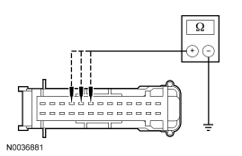
|
Yes GO to G12. No GO to G11. | ||||||||
| G11 CHECK MEMORY SET NO. 1 AND NO. 2 FOR A SHORT TO GROUND | |||||||||
|
Yes INSTALL a new driver seat control switch. REPEAT the self-test, CLEAR the DTCs. DISCONNECT the battery ground cable. DISCONNECT the restraint system diagnostic tool from driver seat side air bag C315. CONNECT driver seat side air bag C315. REPOWER the SRS. REFER to Section 501-20B. No REPAIR the affected circuit for a short to ground. CARRY OUT the driver seat control switch component test to verify the switch has not been damaged. Refer to Wiring Diagrams Cell 149 for schematic and connector information. REPEAT the self-test, CLEAR the DTCs. DISCONNECT the battery ground cable. DISCONNECT the restraint system diagnostic tool from driver seat side air bag C315. CONNECT driver seat side air bag C315. REPOWER the SRS. REFER to Section 501-20B. | ||||||||
| G12 CHECK CIRCUITS 270 (BN/OG), 267 (BN/LG) AND 268 (BK/OG) FOR AN OPEN | |||||||||
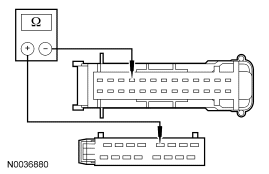
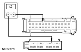
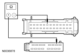
|
Yes GO to G15. No REPAIR the affected circuit for an open. REPEAT the self-test, CLEAR the DTCs. DISCONNECT the battery ground cable. DISCONNECT the restraint system diagnostic tool from driver seat side air bag C315. CONNECT driver seat side air bag C315. REPOWER the SRS. REFER to Section 501-20B. | ||||||||
| G13 CHECK CIRCUIT 272 (WH/OG) FOR AN OPEN | |||||||||
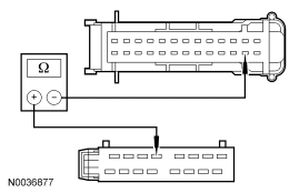
|
Yes GO to G15. No REPAIR circuit 272 (WH/OG) for an open. REPEAT the self-test, CLEAR the DTCs. DISCONNECT the battery ground cable. DISCONNECT the restraint system diagnostic tool from driver seat side air bag C315. CONNECT driver seat side air bag C315. REPOWER the SRS. REFER to Section 501-20B. | ||||||||
| G14 CHECK CIRCUIT 272 (WH/OG) FOR A SHORT TO GROUND | |||||||||
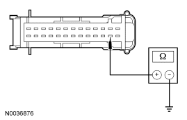
|
Yes INSTALL a new driver seat control switch. REPEAT the self-test, CLEAR the DTCs. DISCONNECT the battery ground cable. DISCONNECT the restraint system diagnostic tool from driver seat side air bag C315. CONNECT driver seat side air bag C315. REPOWER the SRS. REFER to Section 501-20B. No REPAIR circuit 272 (WH/OG) for a short to ground. CARRY OUT the driver seat control switch component test to verify the switch has not been damaged. Refer to Wiring Diagrams Cell 149 for schematic and connector information. REPEAT the self-test, CLEAR the DTCs. DISCONNECT the battery ground cable. DISCONNECT the restraint system diagnostic tool from driver seat side air bag C315. CONNECT driver seat side air bag C315. REPOWER the SRS. REFER to Section 501-20B. | ||||||||
| G15 CHECK MEMORY SET/RECALL SWITCH | |||||||||
|
Yes INSTALL a new DDM. REFER to Section 419-10 for additional information. REPEAT the self-test, CLEAR the DTCs. DISCONNECT the battery ground cable. DISCONNECT the restraint system diagnostic tool from driver seat side air bag C315. CONNECT driver seat side air bag C315. REPOWER the SRS. REFER to Section 501-20B. No INSTALL a new driver seat control switch. REPEAT the self-test, CLEAR the DTCs. DISCONNECT the battery ground cable. DISCONNECT the restraint system diagnostic tool from driver seat side air bag C315. CONNECT driver seat side air bag C315. REPOWER the SRS. REFER to Section 501-20B. |
Pinpoint Test H: Easy Exit/Easy Entry Does Not Operate Correctly
NOTE: The driver power seat easy entry/easy exit feature can be enabled/disabled. Check that the feature is enabled before continuing diagnostics. Refer to Section 418-01 or the owner's literature.
Normal Operation
The easy exit function moves the seat backwards about 2 inches when the ignition key is removed from the ignition switch. The DSM receives a key out command over the SCP communication network and powers the driver seat REARWARD. This function will not operate if the seat is less than the travel distance to the end of the track or the function has been deactivated. The DSM will also cancel this operation if a valid input command is received, such as the seat control switch or memory recall request.
The DSM will record the current seat position before powering the seat for an easy exit function. This recorded position will be used to return the seat to this position on the easy entry operation. During easy entry operation, the seat is returned to the position previous to the easy exit operation. Easy entry operation will be cancelled if a valid input command is received by the DSM.
Possible Causes
A memory seat with an inoperative easy exit/easy entry feature can be caused by:
- wiring, terminals or connectors (SCP communication concern).
- a faulty key-in ignition switch.
- a faulty memory power seat track.
- a faulty DSM.
- a faulty lighting control module (LCM).
PINPOINT TEST H: EASY EXIT/EASY ENTRY DOES NOT OPERATE CORRECTLY
| Test Step | Result / Action to Take |
|---|---|
| H1 CHECK THE DRIVER SEAT OPERATION | |
|
Yes GO to H2. No GO to Symptom Chart to diagnose the inoperative seat function. |
| H2 CHECK THE EASY EXIT OPERATION | |
|
Yes GO to H5. No GO to H3. |
| H3 CHECK THE LIGHTING CONTROL MODULE (LCM) FOR CORRECT INPUTS | |
|
Yes GO to H4. No REFER to Section 211-05 to diagnose the ignition switch concern. |
| H4 CHECK FOR DTCS FROM THE DRIVER SEAT MODULE (DSM) | |
|
Yes If DTC B1665, B1962 or B1965 are retrieved, Go To Pinpoint Test D. REFER to the Diagnostic Trouble Code (DTC) Index in this section for additional DSM DTC diagnosis or Section 419-10 to diagnose all other DSM DTC concerns. No INSTALL a new DSM. REFER to Section 419-10 for additional information. REPEAT the self-test, CLEAR the DTCs. |
| H5 CHECK THE EASY ENTRY OPERATION | |
|
Yes The system is operating correctly at this time. INSTRUCT the customer on the correct operation of the system. No GO to H6. |
| H6 CHECK FOR DTCS FROM THE LCM | |
|
Yes REFER to the Diagnostic Trouble Code (DTC) Index in Section 419-10 to diagnose the LCM concern. No GO to H7. |
| H7 CHECK DSM DTCs | |
|
Yes REFER to the Diagnostic Trouble Code (DTC) Index to diagnose the DTCs. No INSTALL a new DSM. REFER to Section 419-10 for additional information. REPEAT the self-test, CLEAR the DTCs. |
Pinpoint Test I: The Heated Seat Is Inoperative — Driver
Refer to Wiring Diagrams Cell 119, Climate Controlled Seats for schematic and connector information.
Normal Operation
The driver heated seat module receives battery voltage feed on circuit 1048 (LB/WH) and ignition voltage feed on circuit 1040 (RD/BK), and is supplied ground on circuit 676 (PK/OG). When the heated seat control switch is pressed with the ignition switch in RUN or START, a ground signal is sent to the heated seat module on circuit 1020 (DG/VT) to command the system ON or OFF in HI heat mode or circuit 1255 (WH/RD) to command the system ON or OFF in LOW heat mode. When commanded ON, a ground signal is supplied to the heated seat switch from the heated seat module on either circuit 1019 (TN/LB) (HI heat mode) or circuit 1018 (LG/OG) (LOW heat mode) illuminating the switch indicator. The heated seat module also supplies voltage to the cushion and backrest heater mats on circuit 1064 (YE/LB) and ground to the heater mats on circuit 1065 (WH/LB). The cushion and backrest heater mats are connected in series and operate together. Temperature is maintained by the heated seat module using a sensor contained within the cushion heater mat. The heated seat module supplies a reference voltage to the temperature sensor on circuit 1060 (BK/LB) and monitors the return signal from the temperature sensor on circuit 1061 (BN/LB) for adjusting the current flow to the heater mats. The heated seat module is designed to remain ON, heating the seat and maintaining temperature until switched OFF or the time-out period occurs.
Possible Causes
An inoperative driver heated seat can be caused by:
- an open fuse.
- faulty wiring, terminals or connectors.
- a faulty heated seat switch.
- a faulty heater mat.
- a faulty heated seat module.
PINPOINT TEST I: THE HEATED SEAT IS INOPERATIVE — DRIVER
| Test Step | Result / Action to Take |
|---|---|
| I1 CHECK THE HEATED SEAT SWITCH INPUT TO THE HEATED SEAT MODULE | |
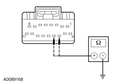
|
Yes GO to I3. No GO to I2. |
| I2 CHECK HEATED SEAT SWITCH GROUND CIRCUIT 57 (BK) | |
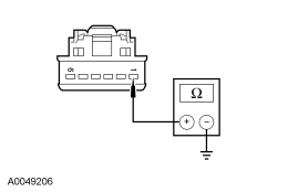
|
Yes INSTALL a new heated seat switch. TEST the system for normal operation. DISCONNECT the battery ground cable. DISCONNECT the restraint system diagnostic tool from driver seat side air bag C315. CONNECT driver seat side air bag C315. REPOWER the SRS. REFER to Section 501-20B. No REPAIR circuit 57 (BK). TEST the system for normal operation. DISCONNECT the battery ground cable. DISCONNECT the restraint system diagnostic tool from driver seat side air bag C315. CONNECT driver seat side air bag C315. REPOWER the SRS. REFER to Section 501-20B. |
| I3 CHECK CIRCUIT 1048 (LB/WH) FOR VOLTAGE TO THE HEATED SEAT MODULE | |
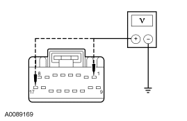
|
Yes GO to I4. No VERIFY BJB fuse 16 (20A) is OK. If OK, REPAIR circuit 1048 (LB/WH). TEST the system for normal operation. DISCONNECT the battery ground cable. DISCONNECT the restraint system diagnostic tool from driver seat side air bag C315. CONNECT driver seat side air bag C315. REPOWER the SRS. REFER to Section 501-20B. |
| I4 CHECK CIRCUIT 1040 (RD/BK) FOR VOLTAGE TO THE HEATED SEAT MODULE | |
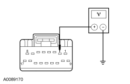
|
Yes GO to I5. No VERIFY CJB fuse 17 (10A) is OK. If OK, REPAIR circuit 1040 (RD/BK). TEST the system for normal operation. DISCONNECT the battery ground cable. DISCONNECT the restraint system diagnostic tool from driver seat side air bag C315. CONNECT driver seat side air bag C315. REPOWER the SRS. REFER to Section 501-20B. |
| I5 CHECK HEATED SEAT MODULE GROUND CIRCUIT 676 (PK/OG) | |
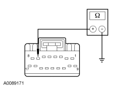
|
Yes GO to I6. No REPAIR circuit 676 (PK/OG). TEST the system for normal operation. DISCONNECT the battery ground cable. DISCONNECT the restraint system diagnostic tool from driver seat side air bag C315. CONNECT driver seat side air bag C315. REPOWER the SRS. REFER to Section 501-20B. |
| I6 CHECK CIRCUIT 1064 (YE/LB) FOR SHORT TO VOLTAGE | |
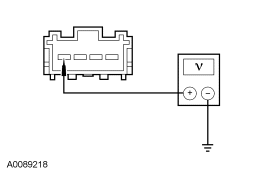
|
Yes REPAIR circuit 1064 (YE/LB). TEST the system for normal operation. DISCONNECT the battery ground cable. DISCONNECT the restraint system diagnostic tool from driver seat side air bag C315. CONNECT driver seat side air bag C315. REPOWER the SRS. REFER to Section 501-20B. No GO to I7. |
| I7 CHECK CIRCUIT 1064 (YE/LB) FOR AN OPEN OR SHORT TO GROUND | |
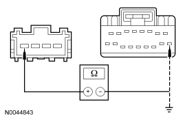
|
Yes GO to I8. No REPAIR circuit 1064 (YE/LB). TEST the system for normal operation. DISCONNECT the battery ground cable. DISCONNECT the restraint system diagnostic tool from driver seat side air bag C315. CONNECT driver seat side air bag C315. REPOWER the SRS. REFER to Section 501-20B. |
| I8 CHECK CIRCUIT 57 (BK) FOR AN OPEN | |
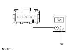
|
Yes GO to I9. No REPAIR circuit 57 (BK). TEST the system for normal operation. DISCONNECT the battery ground cable. DISCONNECT the restraint system diagnostic tool from driver seat side air bag C315. CONNECT driver seat side air bag C315. REPOWER the SRS. REFER to Section 501-20B. |
| I9 CHECK HEATED SEAT ELEMENTS FOR SHORT TO GROUND OR AN OPEN | |
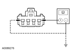
|
Yes GO to I11. No GO to I10. |
| I10 CHECK THE SEAT BACK HEATER | |
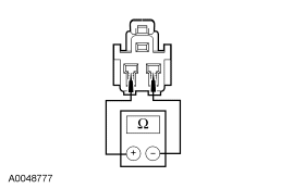
|
Yes INSTALL a new driver seat cushion heater. TEST the system for normal operation. DISCONNECT the battery ground cable. DISCONNECT the restraint system diagnostic tool from driver seat side air bag C315. CONNECT driver seat side air bag C315. REPOWER the SRS. REFER to Section 501-20B. No INSTALL a new driver seat back heater. TEST the system for normal operation. DISCONNECT the battery ground cable. DISCONNECT the restraint system diagnostic tool from driver seat side air bag C315. CONNECT driver seat side air bag C315. REPOWER the SRS. REFER to Section 501-20B. |
| I11 CHECK THE HEATED SEAT TEMPERATURE SENSOR AND CIRCUITS FOR A SHORT TO VOLTAGE | |
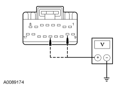
|
Yes REPAIR the affected circuit. TEST the system for normal operation. DISCONNECT the battery ground cable. DISCONNECT the restraint system diagnostic tool from driver seat side air bag C315. CONNECT driver seat side air bag C315. REPOWER the SRS. REFER to Section 501-20B. No GO to I12. |
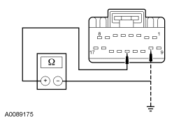
| I12 CHECK THE HEATED SEAT TEMPERATURE SENSOR AND CIRCUITS | |
|
Yes INSTALL a new heated seat module. TEST the system for normal operation. DISCONNECT the battery ground cable. DISCONNECT the restraint system diagnostic tool from driver seat side air bag C315. CONNECT driver seat side air bag C315. REPOWER the SRS. REFER to Section 501-20B. No GO to I13. |
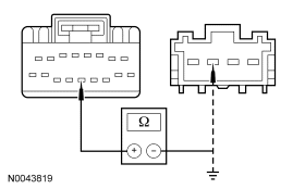
| I13 CHECK CIRCUIT 1061 (BN/LB) FOR AN OPEN OR SHORT TO GROUND | |
|
Yes GO to I14. No REPAIR circuit 1061 (BN/LB). TEST the system for normal operation. DISCONNECT the battery ground cable. DISCONNECT the restraint system diagnostic tool from driver seat side air bag C315. CONNECT driver seat side air bag C315. REPOWER the SRS. REFER to Section 501-20B. |
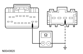
| I14 CHECK CIRCUIT 1060 (BK/LB) FOR AN OPEN OR SHORT TO GROUND | |
|
Yes INSTALL a new driver seat cushion heater. TEST the system for normal operation. DISCONNECT the battery ground cable. DISCONNECT the restraint system diagnostic tool from driver seat side air bag C315. CONNECT driver seat side air bag C315. REPOWER the SRS. REFER to Section 501-20B. No REPAIR circuit 1060 (BK/LB). TEST the system for normal operation. DISCONNECT the battery ground cable. DISCONNECT the restraint system diagnostic tool from driver seat side air bag C315. CONNECT driver seat side air bag C315. REPOWER the SRS. REFER to Section 501-20B. |
Pinpoint Test J: The Heated Seat Is Inoperative — Passenger
Refer to Wiring Diagrams Cell 119, Climate Controlled Seats for schematic and connector information.
Normal Operation
The passenger heated seat module receives battery voltage feed on circuit 1048 (LB/WH) and ignition voltage feed on circuit 1040 (RD/BK), and is supplied ground on circuit 676 (PK/OG). When the heated seat control switch is pressed with the ignition switch in RUN or START, a ground signal is sent to the heated seat module on circuit 581 (RD) to command the system ON or OFF in HI heat mode or circuit 1256 (WH/YE) to command the system ON or OFF in LOW heat mode. When commanded ON, a ground signal is supplied to the heated seat switch from the heated seat module on either circuit 580 (BN) (HI heat mode) or circuit 579 (BK/OG) (LOW heat mode) illuminating the switch indicator. The heated seat module also supplies voltage to the cushion and backrest heater mats on circuit 1064 (YE/LB) and ground to the heater mats on circuit 1065 (WH/LB). The cushion and backrest heater mats are connected in series and operate together. Temperature is maintained by the heated seat module using a sensor contained within the cushion heater mat. The heated seat module supplies a reference voltage to the temperature sensor on circuit 1060 (BK/LB) and monitors the return signal from the temperature sensor on circuit 1061 (BN/LB) for adjusting the current flow to the heater mats. The heated seat module is designed to remain ON, heating the seat and maintaining temperature until switched OFF or the time-out period occurs.
Possible Causes
An inoperative passenger heated seat can be caused by:
- an open fuse.
- faulty wiring, terminals or connectors.
- a faulty heated seat switch.
- a faulty heater mat.
- a faulty heated seat module.
PINPOINT TEST J: THE HEATED SEAT IS INOPERATIVE — PASSENGER
| Test Step | Result / Action to Take |
|---|---|
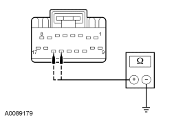
| J1 CHECK THE HEATED SEAT SWITCH INPUT TO THE HEATED SEAT MODULE | |
|
Yes GO to J3. No GO to J2. |
| J2 CHECK HEATED SEAT SWITCH GROUND CIRCUIT 57 (BK) | |
|
Yes INSTALL a new heated seat switch. TEST the system for normal operation. DISCONNECT the battery ground cable. DISCONNECT the restraint system diagnostic tool from passenger seat side air bag C316. CONNECT passenger seat side air bag C316. REPOWER the SRS. REFER to Section 501-20B. No REPAIR circuit 57 (BK). TEST the system for normal operation. DISCONNECT the battery ground cable. DISCONNECT the restraint system diagnostic tool from passenger seat side air bag C316. CONNECT passenger seat side air bag C316. REPOWER the SRS. REFER to Section 501-20B. |
| J3 CHECK CIRCUIT 1048 (LB/WH) FOR VOLTAGE TO THE HEATED SEAT MODULE | |
|
Yes GO to J4. No VERIFY BJB fuse 16 (20A) is OK. If OK, REPAIR circuit 1048 (LB/WH). TEST the system for normal operation. DISCONNECT the battery ground cable. DISCONNECT the restraint system diagnostic tool from passenger seat side air bag C316. CONNECT passenger seat side air bag C316. REPOWER the SRS. REFER to Section 501-20B. |
| J4 CHECK CIRCUIT 1040 (RD/BK) FOR VOLTAGE TO THE HEATED SEAT MODULE | |
|
Yes GO to J5. No VERIFY CJB fuse 17 (10A) is OK. If OK, REPAIR circuit 1040 (RD/BK). TEST the system for normal operation. DISCONNECT the battery ground cable. DISCONNECT the restraint system diagnostic tool from passenger seat side air bag C316. CONNECT passenger seat side air bag C316. REPOWER the SRS. REFER to Section 501-20B. |
| J5 CHECK HEATED SEAT MODULE GROUND CIRCUIT 676 (PK/OG) | |
|
Yes GO to J6. No REPAIR circuit 676 (PK/OG). TEST the system for normal operation. DISCONNECT the battery ground cable. DISCONNECT the restraint system diagnostic tool from passenger seat side air bag C316. CONNECT passenger seat side air bag C316. REPOWER the SRS. REFER to Section 501-20B. |
| J6 CHECK CIRCUIT 1064 (YE/LB) FOR SHORT TO VOLTAGE | |
|
Yes REPAIR circuit 1064 (YE/LB). TEST the system for normal operation. DISCONNECT the battery ground cable. DISCONNECT the restraint system diagnostic tool from passenger seat side air bag C316. CONNECT passenger seat side air bag C316. REPOWER the SRS. REFER to Section 501-20B. No GO to J7. |
| J7 CHECK CIRCUIT 1064 (YE/LB) FOR AN OPEN OR SHORT TO GROUND | |
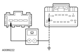
|
Yes GO to J8. No REPAIR circuit 1064 (YE/LB). TEST the system for normal operation. DISCONNECT the battery ground cable. DISCONNECT the restraint system diagnostic tool from passenger seat side air bag C316. CONNECT passenger seat side air bag C316. REPOWER the SRS. REFER to Section 501-20B. |
| J8 CHECK CIRCUIT 57 (BK) FOR AN OPEN | |
|
Yes GO to J9. No REPAIR circuit 57 (BK). TEST the system for normal operation. DISCONNECT the battery ground cable. DISCONNECT the restraint system diagnostic tool from passenger seat side air bag C316. CONNECT passenger seat side air bag C316. REPOWER the SRS. REFER to Section 501-20B. |
| J9 CHECK HEATER MATS FOR SHORT TO GROUND OR AN OPEN | |
|
Yes GO to J11. No GO to J10. |
| J10 CHECK THE SEAT BACK HEATER | |
|
Yes INSTALL a new passenger seat cushion heater. TEST the system for normal operation. DISCONNECT the battery ground cable. DISCONNECT the restraint system diagnostic tool from passenger seat side air bag C316. CONNECT passenger seat side air bag C316. REPOWER the SRS. REFER to Section 501-20B. No INSTALL a new passenger seat back heater. TEST the system for normal operation. DISCONNECT the battery ground cable. DISCONNECT the restraint system diagnostic tool from passenger seat side air bag C316. CONNECT passenger seat side air bag C316. REPOWER the SRS. REFER to Section 501-20B. |
| J11 CHECK THE HEATED SEAT TEMPERATURE SENSOR AND CIRCUITS FOR A SHORT TO VOLTAGE | |
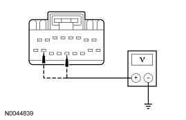
|
Yes REPAIR the affected circuit. TEST the system for normal operation. DISCONNECT the battery ground cable. DISCONNECT the restraint system diagnostic tool from passenger seat side air bag C316. CONNECT passenger seat side air bag C316. REPOWER the SRS. REFER to Section 501-20B. No GO to J12. |
| J12 CHECK THE HEATED SEAT TEMPERATURE SENSOR AND CIRCUITS | |
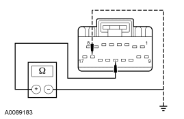
|
Yes INSTALL a new heated seat module. TEST the system for normal operation. DISCONNECT the battery ground cable. DISCONNECT the restraint system diagnostic tool from passenger seat side air bag C316. CONNECT passenger seat side air bag C316. REPOWER the SRS. REFER to Section 501-20B. No GO to J13. |
| J13 CHECK CIRCUIT 1061 (BN/LB) FOR AN OPEN OR SHORT TO GROUND | |
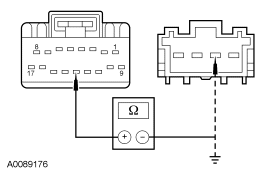
|
Yes GO to J14. No REPAIR circuit 1061 (BN/LB). TEST the system for normal operation. DISCONNECT the battery ground cable. DISCONNECT the restraint system diagnostic tool from passenger seat side air bag C316. CONNECT passenger seat side air bag C316. REPOWER the SRS. REFER to Section 501-20B. |
| J14 CHECK CIRCUIT 1060 (BK/LB) FOR AN OPEN OR SHORT TO GROUND | |
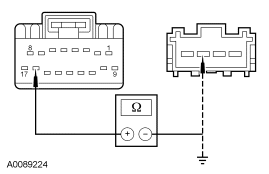
|
Yes INSTALL a new passenger seat cushion heater. TEST the system for normal operation. DISCONNECT the battery ground cable. DISCONNECT the restraint system diagnostic tool from passenger seat side air bag C316. CONNECT passenger seat side air bag C316. REPOWER the SRS. REFER to Section 501-20B. No REPAIR circuit 1060 (BK/LB). TEST the system for normal operation. DISCONNECT the battery ground cable. DISCONNECT the restraint system diagnostic tool from passenger seat side air bag C316. CONNECT passenger seat side air bag C316. REPOWER the SRS. REFER to Section 501-20B. |
Pinpoint Test K: The Heated Seat Is Inoperative — Driver, Does Not Operate In High
Refer to Wiring Diagrams Cell 119, Climate Controlled Seats for schematic and connector information.
Normal Operation
The driver heated seat module receives battery voltage feed on circuit 1048 (LB/WH), ignition voltage feed on circuit 1040 (RD/BK) and is supplied ground on circuit 676 (PK/OG). When the heated seat control switch is pressed with the ignition switch in RUN or START, a ground signal is sent to the heated seat module on circuit 1020 (DG/VT) to command the system ON or OFF in HI heat mode.
Possible Causes
A driver heated seat that does not operate in HI can be caused by:
- faulty wiring, terminals or connectors.
- a faulty heated seat switch.
- a faulty heated seat module.
PINPOINT TEST K: THE HEATED SEAT IS INOPERATIVE — DRIVER, DOES NOT OPERATE IN HIGH
| Test Step | Result / Action to Take |
|---|---|
| K1 CHECK THE HEATED SEAT SWITCH INPUT TO THE HEATED SEAT MODULE | |
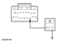
|
Yes INSTALL a new heated seat module. TEST the system for normal operation. DISCONNECT the battery ground cable. DISCONNECT the restraint system diagnostic tool from driver seat side air bag C315. CONNECT driver seat side air bag C315. REPOWER the SRS. REFER to Section 501-20B. No GO to K2. |
| K2 CHECK CIRCUIT 1020 (DG/VT) FOR OPEN OR SHORT TO GROUND | |
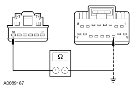
|
Yes GO to K3. No REPAIR circuit 1020 (DG/VT). TEST the system for normal operation. DISCONNECT the battery ground cable. DISCONNECT the restraint system diagnostic tool from driver seat side air bag C315. CONNECT driver seat side air bag C315. REPOWER the SRS. REFER to Section 501-20B. |
| K3 CHECK CIRCUIT 1020 (DG/VT) FOR SHORT TO VOLTAGE | |
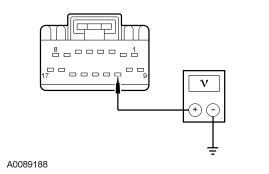
|
Yes REPAIR circuit 1020 (DG/VT). TEST the system for normal operation. DISCONNECT the battery ground cable. DISCONNECT the restraint system diagnostic tool from driver seat side air bag C315. CONNECT driver seat side air bag C315. REPOWER the SRS. REFER to Section 501-20B. No INSTALL a new heated seat switch. TEST the system for normal operation. DISCONNECT the battery ground cable. DISCONNECT the restraint system diagnostic tool from driver seat side air bag C315. CONNECT driver seat side air bag C315. REPOWER the SRS. REFER to Section 501-20B. |
Pinpoint Test L: The Heated Seat Is Inoperative — Driver, Does Not Operate In Low
Refer to Wiring Diagrams Cell 119, Climate Controlled Seats for schematic and connector information.
Normal Operation
The driver heated seat module receives battery voltage feed on circuit 1048 (LB/WH), ignition voltage feed on circuit 1040 (RD/BK) and is supplied ground on circuit 676 (PK/OG). When the heated seat control switch is pressed with the ignition switch in RUN or START, a ground signal is sent to the heated seat module on circuit 1255 (WH/RD) to command the system ON or OFF in LOW heat mode.
Possible Causes
A driver heated seat that does not operate in LOW can be caused by:
- faulty wiring, terminals or connectors.
- a faulty heated seat switch.
- a faulty heated seat module.
PINPOINT TEST L: THE HEATED SEAT IS INOPERATIVE — DRIVER, DOES NOT OPERATE IN LOW
| Test Step | Result / Action to Take |
|---|---|
| L1 CHECK THE HEATED SEAT SWITCH INPUT TO THE HEATED SEAT MODULE | |
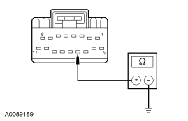
|
Yes INSTALL a new heated seat module. TEST the system for normal operation. DISCONNECT the battery ground cable. DISCONNECT the restraint system diagnostic tool from driver seat side air bag C315. CONNECT driver seat side air bag C315. REPOWER the SRS. REFER to Section 501-20B. No GO to L2. |
| L2 CHECK CIRCUIT 1255 (WH/RD) FOR OPEN OR SHORT TO GROUND | |
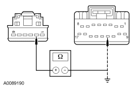
|
Yes GO to L3. No REPAIR circuit 1255 (WH/RD). TEST the system for normal operation. DISCONNECT the battery ground cable. DISCONNECT the restraint system diagnostic tool from driver seat side air bag C315. CONNECT driver seat side air bag C315. REPOWER the SRS. REFER to Section 501-20B. |
| L3 CHECK CIRCUIT 1255 (WH/RD) FOR SHORT TO VOLTAGE | |
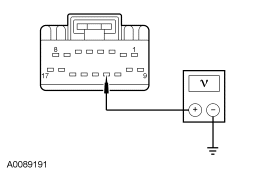
|
Yes REPAIR circuit 1255 (WH/RD). TEST the system for normal operation. DISCONNECT the battery ground cable. DISCONNECT the restraint system diagnostic tool from driver seat side air bag C315. CONNECT driver seat side air bag C315. REPOWER the SRS. REFER to Section 501-20B. No INSTALL a new heated seat switch. TEST the system for normal operation. DISCONNECT the battery ground cable. DISCONNECT the restraint system diagnostic tool from driver seat side air bag C315. CONNECT driver seat side air bag C315. REPOWER the SRS. REFER to Section 501-20B. |
Pinpoint Test M: The Heated Seat Is Inoperative — Passenger, Does Not Operate In High
Refer to Wiring Diagrams Cell 119, Climate Controlled Seats for schematic and connector information.
Normal Operation
The driver heated seat module receives battery voltage feed on circuit 1048 (LB/WH), ignition voltage feed on circuit 1040 (RD/BK) and is supplied ground on circuit 676 (PK/OG). When the heated seat control switch is pressed with the ignition switch in RUN or START, a ground signal is sent to the heated seat module on circuit 581 (RD) to command the system ON or OFF in HI heat mode.
Possible Causes
A passenger heated seat that does not operate in HI can be caused by:
- faulty wiring, terminals or connectors.
- a faulty heated seat switch.
- a faulty heated seat module.
PINPOINT TEST M: THE HEATED SEAT IS INOPERATIVE — PASSENGER, DOES NOT OPERATE IN HIGH
| Test Step | Result / Action to Take |
|---|---|
| M1 CHECK THE HEATED SEAT SWITCH INPUT TO THE HEATED SEAT MODULE | |
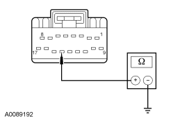
|
Yes INSTALL a new heated seat module. TEST the system for normal operation. DISCONNECT the battery ground cable. DISCONNECT the restraint system diagnostic tool from passenger seat side air bag C316. CONNECT passenger seat side air bag C316. REPOWER the SRS. REFER to Section 501-20B. No GO to M2. |
| M2 CHECK CIRCUIT 581 (RD), 1020 (DG/VT) FOR OPEN OR SHORT TO GROUND | |
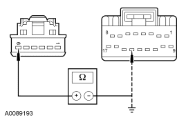
|
Yes GO to M3. No REPAIR circuit 581 (RD) or 1020 (DG/VT). TEST the system for normal operation. DISCONNECT the battery ground cable. DISCONNECT the restraint system diagnostic tool from passenger seat side air bag C316. CONNECT passenger seat side air bag C316. REPOWER the SRS. REFER to Section 501-20B. |
| M3 CHECK CIRCUIT 581 (RD) FOR SHORT TO VOLTAGE | |
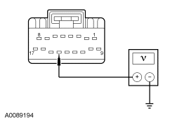
|
Yes REPAIR circuit 581 (RD). TEST the system for normal operation. DISCONNECT the battery ground cable. DISCONNECT the restraint system diagnostic tool from passenger seat side air bag C316. CONNECT passenger seat side air bag C316. REPOWER the SRS. REFER to Section 501-20B. No INSTALL a new heated seat switch. TEST the system for normal operation. DISCONNECT the battery ground cable. DISCONNECT the restraint system diagnostic tool from passenger seat side air bag C316. CONNECT passenger seat side air bag C316. REPOWER the SRS. REFER to Section 501-20B. |
Pinpoint Test N: The Heated Seat Is Inoperative — Passenger, Does Not Operate In Low
Refer to Wiring Diagrams Cell 119, Climate Controlled Seats for schematic and connector information.
Normal Operation
The driver heated seat module receives battery voltage feed on circuit 1048 (LB/WH), ignition voltage feed on circuit 1040 (RD/BK) and is supplied ground on circuit 676 (PK/OG). When the heated seat control switch is pressed with the ignition switch in RUN or START, a ground signal is sent to the heated seat module on circuit 1256 (WH/YE) to command the system ON or OFF in LOW heat mode.
Possible Causes
A passenger heated seat that does not operate in LOW can be caused by:
- faulty wiring, terminals or connectors.
- a faulty heated seat switch.
- a faulty heated seat module.
PINPOINT TEST N: THE HEATED SEAT IS INOPERATIVE — PASSENGER, DOES NOT OPERATE IN LOW
| Test Step | Result / Action to Take |
|---|---|
| N1 CHECK THE HEATED SEAT SWITCH INPUT TO THE HEATED SEAT MODULE | |
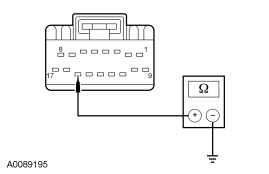
|
Yes INSTALL a new heated seat module. TEST the system for normal operation. DISCONNECT the battery ground cable. DISCONNECT the restraint system diagnostic tool from passenger seat side air bag C316. CONNECT passenger seat side air bag C316. REPOWER the SRS. REFER to Section 501-20B. No GO to N2. |
| N2 CHECK CIRCUIT 1256 (WH/YE), 1255 (WH/RD) FOR OPEN OR SHORT TO GROUND | |
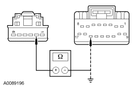
|
Yes GO to N3. No REPAIR the circuit. TEST the system for normal operation. DISCONNECT the battery ground cable. DISCONNECT the restraint system diagnostic tool from passenger seat side air bag C316. CONNECT passenger seat side air bag C316. REPOWER the SRS. REFER to Section 501-20B. |
| N3 CHECK CIRCUIT 1256 (WH/YE) FOR SHORT TO VOLTAGE | |
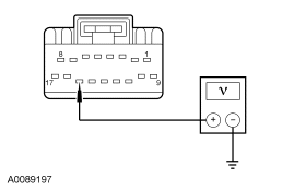
|
Yes REPAIR circuit 1256 (WH/YE). TEST the system for normal operation. DISCONNECT the battery ground cable. DISCONNECT the restraint system diagnostic tool from passenger seat side air bag C316. CONNECT passenger seat side air bag C316. REPOWER the SRS. REFER to Section 501-20B. No INSTALL a new heated seat switch. TEST the system for normal operation. DISCONNECT the battery ground cable. DISCONNECT the restraint system diagnostic tool from passenger seat side air bag C316. CONNECT passenger seat side air bag C316. REPOWER the SRS. REFER to Section 501-20B. |
Pinpoint Test O: The Heated Seat Is Inoperative — Left Rear
Refer to Wiring Diagrams Cell 119, Climate Controlled Seats for schematic and connector information.
Normal Operation
The left rear heated seat module receives battery voltage feed on circuit 1445 (RD/LG), ignition voltage feed on circuit 1040 (RD/BK) and is supplied ground on circuit 57 (BK). When the heated seat control switch is pressed with the ignition switch in RUN or START, a ground signal is sent to the heated seat module on circuit 1020 (DG/VT) to command the system ON or OFF in HI heat mode or circuit 1255 (WH/RD) to command the system ON or OFF in LOW heat mode. When commanded ON, a ground signal is supplied to the heated seat switch from the heated seat module on either circuit 1019 (TN/LB) (HI heat mode) or circuit 1018 (LG/OG) illuminating the switch indicator. The heated seat module also supplies voltage to the cushion and backrest heater mats on circuit 1064 (YE/LB) and ground to the heater mats on circuit 1065 (WH/LB). The cushion and backrest heater mats are connected in series and operate together. Temperature is maintained by the heated seat module using a sensor contained within the cushion heater mat. The heated seat module supplies a reference voltage to the temperature sensor on circuit 1060 (BK/LB) and monitors the return signal from the temperature sensor on circuit 1061 (BN/LB) for adjusting the current flow to the heater mats. The heated seat module is designed to remain ON, heating the seat and maintaining temperature until switched OFF or the time-out period occurs.
Possible Causes
An inoperative left rear heated seat can be caused by:
- an open fuse.
- faulty wiring, terminals or connectors.
- a faulty heated seat switch.
- a faulty heater mat.
- a faulty heated seat module.
PINPOINT TEST O: THE HEATED SEAT IS INOPERATIVE — LEFT REAR
| Test Step | Result / Action to Take |
|---|---|
| O1 CHECK THE HEATED SEAT SWITCH INPUT TO THE HEATED SEAT MODULE | |
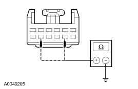
|
Yes GO to O3. No GO to O2. |
| O2 CHECK HEATED SEAT SWITCH GROUND CIRCUIT 57 (BK) | |
|
Yes INSTALL a new heated seat switch. TEST the system for normal operation. No REPAIR circuit 57 (BK). TEST the system for normal operation. |
| O3 CHECK CIRCUIT 1445 (RD/LG) FOR VOLTAGE TO THE HEATED SEAT MODULE | |
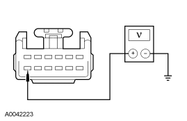
|
Yes GO to O4. No VERIFY BJB fuse 2 (20A) is OK. If OK, REPAIR circuit 1445 (RD/LG). TEST the system for normal operation. |
| O4 CHECK CIRCUIT 1040 (RD/BK) FOR VOLTAGE TO THE HEATED SEAT MODULE | |
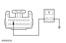
|
Yes GO to O5. No VERIFY CJB fuse 17 (10A) is OK. If OK, REPAIR circuit 1040 (RD/BK). TEST the system for normal operation. |
| O5 CHECK HEATED SEAT MODULE GROUND CIRCUIT 57 (BK) | |
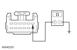
|
Yes GO to O6. No REPAIR circuit 57 (BK). TEST the system for normal operation. |
| O6 CHECK THE SEAT CUSHION HEATER AND THE SEAT BACK HEATER CIRCUITS | |
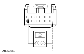
|
Yes GO to O7. No GO to O13. |
| O7 CHECK THE SEAT CUSHION HEATER AND THE SEAT BACK HEATER CIRCUITS FOR A SHORT TO VOLTAGE | |
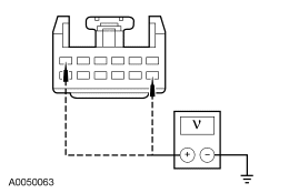
|
Yes GO to O8. No GO to O9. |
| O8 CHECK CIRCUIT 1064 (YE/LB) AND CIRCUIT 1065 (WH/LB) FOR A SHORT TO VOLTAGE | |
|
Yes REPAIR the affected circuit. TEST the system for normal operation. No REPAIR circuit 1064 (YE/LB) between the left rear seat cushion heater C3167 and the left rear seat back heater C3168. TEST the system for normal operation. |
| O9 CHECK THE HEATED SEAT TEMPERATURE SENSOR CIRCUITS FOR A SHORT TO VOLTAGE | |
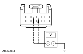
|
Yes REPAIR the affected circuit. TEST the system for normal operation. No GO to O10. |
| O10 CHECK THE HEATED SEAT TEMPERATURE SENSOR CIRCUITS | |
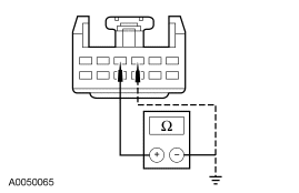
|
Yes INSTALL a new left rear heated seat module. TEST the system for normal operation. No GO to O11. |
| O11 CHECK CIRCUIT 1061 (BN/LB) FOR AN OPEN OR SHORT TO GROUND | |
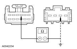
|
Yes GO to O12. No REPAIR circuit 1061 (BN/LB). TEST the system for normal operation. |
| O12 CHECK CIRCUIT 1060 (BK/LB) FOR AN OPEN OR SHORT TO GROUND | |
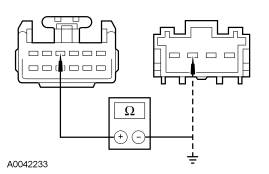
|
Yes INSTALL a new left rear seat cushion heater. TEST the system for normal operation. No REPAIR circuit 1060 (BK/LB). TEST the system for normal operation. |
| O13 CHECK CIRCUIT 1064 (YE/LB) FOR OPEN OR SHORT TO GROUND | |
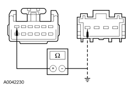
|
Yes GO to O14. No REPAIR circuit 1064 (YE/LB). TEST the system for normal operation. |
| O14 CHECK CIRCUIT 1065 (WH/LB) FOR OPEN OR SHORT TO GROUND | |
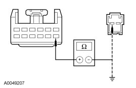
|
Yes GO to O15. No REPAIR circuit 1065 (WH/LB). TEST the system for normal operation. |
| O15 CHECK CIRCUIT 1064 (YE/LB) FOR OPEN OR SHORT TO GROUND BETWEEN THE HEATED SEAT MODULE AND THE SEAT BACK HEATER | |
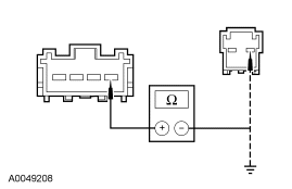
|
Yes GO to O16. No REPAIR circuit 1064 (YE/LB). TEST the system for normal operation. |
| O16 CHECK THE SEAT BACK HEATER | |
|
Yes INSTALL a new left rear seat cushion heater. TEST the system for normal operation. No INSTALL a new left rear seat back heater. TEST the system for normal operation. |
Pinpoint Test P: The Heated Seat Is Inoperative — Right Rear
Refer to Wiring Diagrams Cell 119, Climate Controlled Seats for schematic and connector information.
Normal Operation
The right rear heated seat module receives battery voltage feed on circuit 1445 (RD/GN), ignition voltage feed on circuit 1040 (RD/BK) and is supplied ground on circuit 57 (BK). When the heated seat control switch is pressed with the ignition switch in RUN or START, a ground signal is sent to the heated seat module on circuit 581 (RD) to command the system ON or OFF in HI heat mode or circuit 1256 (WH/YE) to command the system ON or OFF in LOW heat mode. When commanded ON, a ground signal is supplied to the heated seat switch from the heated seat module on either circuit 580 (BN) (HIGH heat mode) or circuit 579 (BK/OG) (LOW heat mode) illuminating the switch indicator. The heated seat module also supplies voltage to the cushion and backrest heater mats on circuit 1064 (YE/LB) and ground to the heater mats on circuit 1065 (WH/LB). The cushion and backrest heater mats are connected in series and operate together. Temperature is maintained by the heated seat module using a sensor contained within the cushion heater mat. The heated seat module supplies a reference voltage to the temperature sensor on circuit 1060 (BK/LB) and monitors the return signal from the temperature sensor on circuit 1061 (BN/LB) for adjusting the current flow to the heater mats. The heated seat module is designed to remain ON, heating the seat and maintaining temperature until switched OFF or the time-out period occurs.
Possible Causes
An inoperative right rear heated seat can be caused by:
- an open fuse.
- faulty wiring, terminals or connectors.
- a faulty heated seat switch.
- a faulty heater mat.
- a faulty heated seat module.
PINPOINT TEST P: THE HEATED SEAT IS INOPERATIVE — RIGHT REAR
| Test Step | Result / Action to Take |
|---|---|
| P1 CHECK THE HEATED SEAT SWITCH INPUT TO THE HEATED SEAT MODULE | |
|
Yes GO to P3. No GO to P2. |
| P2 CHECK HEATED SEAT SWITCH GROUND CIRCUIT 57 (BK) | |
|
Yes INSTALL a new heated seat switch. TEST the system for normal operation. No REPAIR circuit 57 (BK). TEST the system for normal operation. |
| P3 CHECK CIRCUIT 1445 (RD/LG) FOR VOLTAGE TO THE HEATED SEAT MODULE | |
|
Yes GO to P4. No VERIFY BJB fuse 2 (20A) is OK. If OK, REPAIR circuit 1445 (RD/LG). TEST the system for normal operation. |
| P4 CHECK CIRCUIT 1040 (RD/BK) FOR VOLTAGE TO THE HEATED SEAT MODULE | |
|
Yes GO to P5. No VERIFY CJB fuse 17 (10A) is OK. If OK, REPAIR circuit 1040 (RD/BK). TEST the system for normal operation. |
| P5 CHECK HEATED SEAT MODULE GROUND CIRCUIT 57 (BK) | |
|
Yes GO to P6. No REPAIR circuit 57 (BK). TEST the system for normal operation. |
| P6 CHECK THE SEAT CUSHION HEATER AND THE SEAT BACK HEATER CIRCUITS | |
|
Yes GO to P7. No GO to P13. |
| P7 CHECK THE SEAT CUSHION HEATER AND THE SEAT BACK HEATER CIRCUITS FOR A SHORT TO VOLTAGE | |
|
Yes GO to P8. No GO to P9. |
| P8 CHECK CIRCUIT 1064 (YE/LB) AND CIRCUIT 1065 (WH/LB) FOR A SHORT TO VOLTAGE | |
|
Yes REPAIR the affected circuit. TEST the system for normal operation. No REPAIR circuit 1064 (YE/LB) between the right rear seat cushion heater C3164 and the right rear seat back heater C3170. TEST the system for normal operation. |
| P9 CHECK THE HEATED SEAT TEMPERATURE SENSOR CIRCUITS FOR A SHORT TO VOLTAGE | |
|
Yes REPAIR the affected circuit. TEST the system for normal operation. No GO to P10. |
| P10 CHECK THE HEATED SEAT TEMPERATURE SENSOR CIRCUITS | |
|
Yes INSTALL a new right rear heated seat module. TEST the system for normal operation. No GO to P11. |
| P11 CHECK CIRCUIT 1061 (BN/LB) FOR AN OPEN OR SHORT TO GROUND | |
|
Yes GO to P12. No REPAIR circuit 1061 (BN/LB). TEST the system for normal operation. |
| P12 CHECK CIRCUIT 1060 (BK/LB) FOR AN OPEN OR SHORT TO GROUND | |
|
Yes INSTALL a new right rear seat cushion heater. TEST the system for normal operation. No REPAIR circuit 1060 (BK/LB). TEST the system for normal operation. |
| P13 CHECK CIRCUIT 1064 (YE/LB) FOR OPEN OR SHORT TO GROUND | |
|
Yes GO to P14. No REPAIR circuit 1064 (YE/LB). TEST the system for normal operation. |
| P14 CHECK CIRCUIT 1065 (WH/LB) FOR OPEN OR SHORT TO GROUND | |
|
Yes GO to P15. No REPAIR circuit 1065 (WH/LB). TEST the system for normal operation. |
| P15 CHECK CIRCUIT 1064 (YE/LB) FOR OPEN OR SHORT TO GROUND BETWEEN THE HEATED SEAT MODULE AND THE SEAT BACK HEATER | |
|
Yes GO to P16. No REPAIR circuit 1064 (YE/LB). TEST the system for normal operation. |
| P16 CHECK THE SEAT BACK HEATER | |
|
Yes INSTALL a new right rear seat cushion heater. TEST the system for normal operation. No INSTALL a new right rear seat back heater. TEST the system for normal operation. |
Pinpoint Test Q: The Heated Seat Is Inoperative — Left Rear, Does Not Operate In High
Refer to Wiring Diagrams Cell 119, Climate Controlled Seats for schematic and connector information.
Normal Operation
The left rear heated seat module receives battery voltage feed on circuit 1445 (RD/LG), ignition voltage feed on circuit 1040 (RD/BK) and is supplied ground on circuit 57 (BK). When the heated seat control switch is pressed with the ignition switch in RUN or START, a ground signal is sent to the heated seat module on circuit 1020 (DG/PK) to command the system ON or OFF (HIGH heat mode).
Possible Causes
A left rear heated seat that does not operate in HI can be caused by:
- faulty wiring, terminals or connectors.
- a faulty heated seat switch.
- a faulty heated seat module.
PINPOINT TEST Q: THE HEATED SEAT IS INOPERATIVE — LEFT REAR, DOES NOT OPERATE IN HIGH
| Test Step | Result / Action to Take |
|---|---|
| Q1 CHECK THE HEATED SEAT SWITCH INPUT TO THE HEATED SEAT MODULE | |
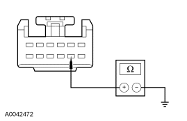
|
Yes INSTALL a new heated seat module. TEST the system for normal operation. No GO to Q2. |
| Q2 CHECK CIRCUIT 1020 (DG/VT) FOR OPEN OR SHORT TO GROUND | |
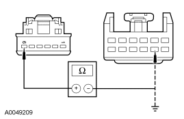
|
Yes GO to Q3. No REPAIR circuit 1020 (DG/VT). TEST the system for normal operation. |
| Q3 CHECK CIRCUIT 1020 (DG/VT) FOR SHORT TO VOLTAGE | |
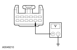
|
Yes INSTALL a new heated seat switch. TEST the system for normal operation. No REPAIR circuit 1020 (DG/VT). TEST the system for normal operation. |
Pinpoint Test R: The Heated Seat Is Inoperative — Left Rear, Does Not Operate In Low
Refer to Wiring Diagrams Cell 119, Climate Controlled Seats for schematic and connector information.
Normal Operation
The left rear heated seat module receives battery voltage feed on circuit 1445 (RD/LG), ignition voltage feed on circuit 1040 (RD/BK) and is supplied ground on circuit 57 (BK). When the heated seat control switch is pressed with the ignition switch in RUN or START, a ground signal is sent to the heated seat module on circuit 1255 (WH/RD) to command the system ON or OFF (LOW heat mode).
Possible Causes
A left rear heated seat that does not operate in LOW can be caused by:
- faulty wiring, terminals or connectors.
- a faulty heated seat switch.
- a faulty heated seat module.
PINPOINT TEST R: THE HEATED SEAT IS INOPERATIVE — LEFT REAR, DOES NOT OPERATE IN LOW
| Test Step | Result / Action to Take |
|---|---|
| R1 CHECK THE HEATED SEAT SWITCH INPUT TO THE HEATED SEAT MODULE | |
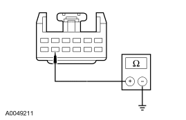
|
Yes INSTALL a new heated seat module. TEST the system for normal operation. No GO to R2. |
| R2 CHECK CIRCUIT 1255 (WH/RD) FOR OPEN OR SHORT TO GROUND | |
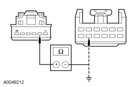
|
Yes GO to R3. No REPAIR circuit 1255 (WH/RD). TEST the system for normal operation. |
| R3 CHECK CIRCUIT 1255 (WH/RD) FOR SHORT TO VOLTAGE | |
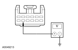
|
Yes INSTALL a new heated seat switch. TEST the system for normal operation. No REPAIR circuit 1255 (WH/RD). TEST the system for normal operation. |
Pinpoint Test S: The Heated Seat Is Inoperative — Right Rear, Does Not Operate In High
Refer to Wiring Diagrams Cell 119, Climate Controlled Seats for schematic and connector information.
Normal Operation
The right rear heated seat module receives battery voltage feed on circuit 1445 (RD/LG), ignition voltage feed on circuit 1040 (RD/BK) and is supplied ground on circuit 57 (BK). When the heated seat control switch is pressed with the ignition switch in RUN or START, a ground signal is sent to the heated seat module on circuit 581 (RD) to command the system ON or OFF (HIGH heat mode).
Possible Causes
A right rear heated seat that does not operate in HI can be caused by:
- faulty wiring, terminals or connectors.
- a faulty heated seat switch.
- a faulty heated seat module.
PINPOINT TEST S: THE HEATED SEAT IS INOPERATIVE — RIGHT REAR, DOES NOT OPERATE IN HIGH
| Test Step | Result / Action to Take |
|---|---|
| S1 CHECK THE HEATED SEAT SWITCH INPUT TO THE HEATED SEAT MODULE | |
|
Yes INSTALL a new heated seat module. TEST the system for normal operation. No GO to S2. |
| S2 CHECK CIRCUIT 581 (RD), 1020 (DG/VT) FOR OPEN OR SHORT TO GROUND | |
|
Yes GO to S3. No REPAIR the affected circuit. TEST the system for normal operation. |
| S3 CHECK CIRCUIT 581 (RD) FOR SHORT TO VOLTAGE | |
|
Yes INSTALL a new heated seat switch. TEST the system for normal operation. No REPAIR circuit 581 (RD). TEST the system for normal operation. |
Pinpoint Test T: The Heated Seat Is Inoperative — Right Rear, Does Not Operate In Low
Refer to Wiring Diagrams Cell 119, Climate Controlled Seats for schematic and connector information.
Normal Operation
The right rear heated seat module receives battery voltage feed on circuit 1445 (RD/LG), ignition voltage feed on circuit 1040 (RD/BK) and is supplied ground on circuit 57 (BK). When the heated seat control switch is pressed with the ignition switch in RUN or START, a ground signal is sent to the heated seat module on circuit 1256 (WH/YE) to command the system ON or OFF (LOW heat mode).
Possible Causes
A right rear heated seat that does not operate in LOW can be caused by:
- faulty wiring, terminals or connectors.
- a faulty heated seat switch.
- a faulty heated seat module.
PINPOINT TEST T: THE HEATED SEAT IS INOPERATIVE — RIGHT REAR, DOES NOT OPERATE IN LOW
| Test Step | Result / Action to Take |
|---|---|
| T1 CHECK THE HEATED SEAT SWITCH INPUT TO THE HEATED SEAT MODULE | |
|
Yes INSTALL a new heated seat module. TEST the system for normal operation. No GO to T2. |
| T2 CHECK CIRCUIT 1256 (WH/YE), 1255 (WH/RD) FOR OPEN OR SHORT TO GROUND | |
|
Yes GO to T3. No REPAIR the affected circuit. TEST the system for normal operation. |
| T3 CHECK CIRCUIT 1256 (WH/YE) FOR SHORT TO VOLTAGE | |
|
Yes INSTALL a new heated seat switch. TEST the system for normal operation. No REPAIR circuit 1256 (WH/YE). TEST the system for normal operation. |
Pinpoint Test U: The Power Lumbar Is Inoperative — Driver
Refer to Wiring Diagrams Cell 122, Power Lumbar Seats for schematic and connector information.
Normal Operation
The lumbar control switch is powered by battery voltage to circuit 566 (DG) and ground to circuit 57 (BK). The lumbar switch toggles voltage and ground directly to the lumbar motor circuits 1094 (PK) and 1097 (BN). The lumbar motor tightens or relaxes a cable connector to the lumbar adjuster.
Possible Causes
An inoperative power lumbar can be caused by:
- a fuse.
- a faulty circuit breaker.
- a faulty circuit.
- a faulty lumbar control switch.
- a faulty lumbar assembly.
PINPOINT TEST U: THE POWER LUMBAR IS INOPERATIVE — DRIVER
| Test Step | Result / Action to Take |
|---|---|
| U1 CHECK CIRCUIT 566 (DG) FOR AN OPEN | |
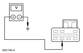
|
Yes GO to U2. No VERIFY battery junction box (BJB) fuse 15 (15A) is OK. If OK, REPAIR the circuit. TEST the system for normal operation. DISCONNECT the battery ground cable. DISCONNECT the restraint system diagnostic tool from driver seat side air bag C315. CONNECT driver seat side air bag C315. REPOWER the SRS. REFER to Section 501-20B. |
| U2 CHECK CIRCUIT 57 (BK) FOR AN OPEN | |
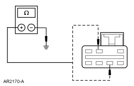
|
Yes GO to U3. No REPAIR the circuit. TEST the system for normal operation. DISCONNECT the battery ground cable. DISCONNECT the restraint system diagnostic tool from driver seat side air bag C315. CONNECT driver seat side air bag C315. REPOWER the SRS. REFER to Section 501-20B. |
| U3 CHECK THE LUMBAR MOTOR | |
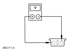
|
Yes INSTALL a new driver power lumbar motor. REFER to Lumbar Motor in this section. TEST the system for normal operation. DISCONNECT the battery ground cable. DISCONNECT the restraint system diagnostic tool from driver seat side air bag C315. CONNECT driver seat side air bag C315. REPOWER the SRS. REFER to Section 501-20B. No GO to U4. |
| U4 CHECK CIRCUIT 1094 (PK) AND CIRCUIT 1097 (BN) FOR A SHORT TO GROUND | |
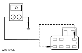
|
Yes GO to U5. No REPAIR the circuit. TEST the system for normal operation. DISCONNECT the battery ground cable. DISCONNECT the restraint system diagnostic tool from driver seat side air bag C315. CONNECT driver seat side air bag C315. REPOWER the SRS. REFER to Section 501-20B. |
| U5 CHECK CIRCUIT 1094 (PK) AND CIRCUIT 1097 (BN) FOR AN OPEN | |
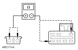
|
Yes INSTALL a new driver power lumbar switch. REFER to Lumbar Control Switch in this section. TEST the system for normal operation. DISCONNECT the battery ground cable. DISCONNECT the restraint system diagnostic tool from driver seat side air bag C315. CONNECT driver seat side air bag C315. REPOWER the SRS. REFER to Section 501-20B. No REPAIR the circuit. TEST the system for normal operation. DISCONNECT the battery ground cable. DISCONNECT the restraint system diagnostic tool from driver seat side air bag C315. CONNECT driver seat side air bag C315. REPOWER the SRS. REFER to Section 501-20B. |
Pinpoint Test V: The Power Lumbar Is Inoperative — Passenger
Refer to Wiring Diagrams Cell 122, Power Lumbar Seats for schematic and connector information.
Normal Operation
The lumbar control switch is powered by battery voltage to circuit 566 (DG) and ground to circuit 57 (BK). The lumbar switch toggles voltage and ground directly to the lumbar motor circuits 1094 (PK) and 1097 (BN). The lumbar motor tightens or relaxes a cable connector to the lumbar adjuster.
Possible Causes
An inoperative power lumbar can be caused by:
- a faulty circuit breaker.
- a faulty circuit.
- a faulty lumbar control switch.
- a faulty lumbar assembly.
PINPOINT TEST V: THE POWER LUMBAR IS INOPERATIVE — PASSENGER
| Test Step | Result / Action to Take |
|---|---|
| V1 CHECK CIRCUIT 566 (DG) FOR AN OPEN | |
|
Yes GO to V2. No VERIFY battery junction box (BJB) fuse 15 (15A) is OK. If OK, REPAIR the circuit. TEST the system for normal operation. DISCONNECT the battery ground cable. DISCONNECT the restraint system diagnostic tool from passenger seat side air bag C316. CONNECT passenger seat side air bag C316. REPOWER the SRS. REFER to Section 501-20B. |
| V2 CHECK CIRCUIT 57 (BK) FOR AN OPEN | |
|
Yes GO to V3. No REPAIR circuit. TEST the system for normal operation. DISCONNECT the battery ground cable. DISCONNECT the restraint system diagnostic tool from passenger seat side air bag C316. CONNECT passenger seat side air bag C316. REPOWER the SRS. REFER to Section 501-20B. |
| V3 CHECK THE LUMBAR MOTOR | |
|
Yes INSTALL a new passenger power lumbar motor. REFER to Lumbar Motor in this section. TEST the system for normal operation. DISCONNECT the battery ground cable. DISCONNECT the restraint system diagnostic tool from passenger seat side air bag C316. CONNECT passenger seat side air bag C316. REPOWER the SRS. REFER to Section 501-20B. No GO to V4. |
| V4 CHECK CIRCUIT 1094 (PK) AND CIRCUIT 1097 (BN) FOR A SHORT TO GROUND | |
|
Yes GO to V5. No REPAIR the circuit. TEST the system for normal operation. DISCONNECT the battery ground cable. DISCONNECT the restraint system diagnostic tool from passenger seat side air bag C316. CONNECT passenger seat side air bag C316. REPOWER the SRS. REFER to Section 501-20B. |
| V5 CHECK CIRCUIT 1094 (PK) AND CIRCUIT 1097 (BN) FOR AN OPEN | |
|
Yes INSTALL a new passenger power lumbar switch. REFER to Lumbar Control Switch in this section. TEST the system for normal operation. DISCONNECT the battery ground cable. DISCONNECT the restraint system diagnostic tool from passenger seat side air bag C316. CONNECT passenger seat side air bag C316. REPOWER the SRS. REFER to Section 501-20B. No REPAIR the circuit. TEST the system for normal operation. DISCONNECT the battery ground cable. DISCONNECT the restraint system diagnostic tool from passenger seat side air bag C316. CONNECT passenger seat side air bag C316. REPOWER the SRS. REFER to Section 501-20B. |
Pinpoint Test W: DTC B1676; Battery Voltage Out Of Range
Refer to Wiring Diagrams Cell 123, Memory Seats for schematic and connector information.
Normal Operation
The DSM is powered by battery voltage from circuit 490 (RD) and is supplied ground on circuit 57 (BK). The DSM monitors the supply voltage input for correct operation. If the module supply voltage is not between 11.5 and 16 volts while in operation, DTC B1676 may result.
Possible Causes
DTC B1676 battery pack voltage out of range can be caused by:
- faulty wiring, terminals or connectors.
- low battery voltage.
- a faulty charging system.
- a faulty DSM.
PINPOINT TEST W: DTC B1676; BATTERY VOLTAGE OUT OF RANGE
| Test Step | Result / Action to Take |
|---|---|
| W1 CHECK FOR RELATED DTCS | |
|
Yes REFER to the Diagnostic Trouble Code (DTC) Index in Section 501-09 to diagnose the DSM concern. No GO to W2. |
| W2 CHECK FOR VOLTAGE AT DRIVER SEAT MODULE (DSM) | |
|
Yes CLEAR the DSM DTCs. CARRY OUT the DSM Self-Test. If DTC B1676 is retrieved, INSTALL a new DSM module. REFER to Section 419-10 for additional information. REPEAT the self-test, CLEAR the DTCs. Otherwise, the system is operating correctly at this time. DISCONNECT the battery ground cable. DISCONNECT the restraint system diagnostic tool from driver seat side air bag C315. CONNECT driver seat side air bag C315. REPOWER the SRS. REFER to Section 501-20B. No REFER to Section 414-02 to diagnose the charging system concern. DISCONNECT the battery ground cable. DISCONNECT the restraint system diagnostic tool from driver seat side air bag C315. CONNECT driver seat side air bag C315. REPOWER the SRS. REFER to Section 501-20B. |
Parts & tools for this job For 2007 Lincoln Town Car
- TOOLTrim removal tool kitSearch: trim removal tool kit
- PARTTouch-up paintSearch: Lincoln touch up paint
- PARTPanel clip assortmentSearch: Lincoln panel clips assortment
Links open Amazon search results in a new tab. As an Amazon Associate I earn from qualifying purchases.
Help keep workshop manuals free
workshop-manuals.com provides free online workshop manuals. If they helped you fix your car, please consider sharing or making a small donation to keep the servers running.
Or make a donation:
Support on Ko-fi