
3 L4-2.3L (2004)
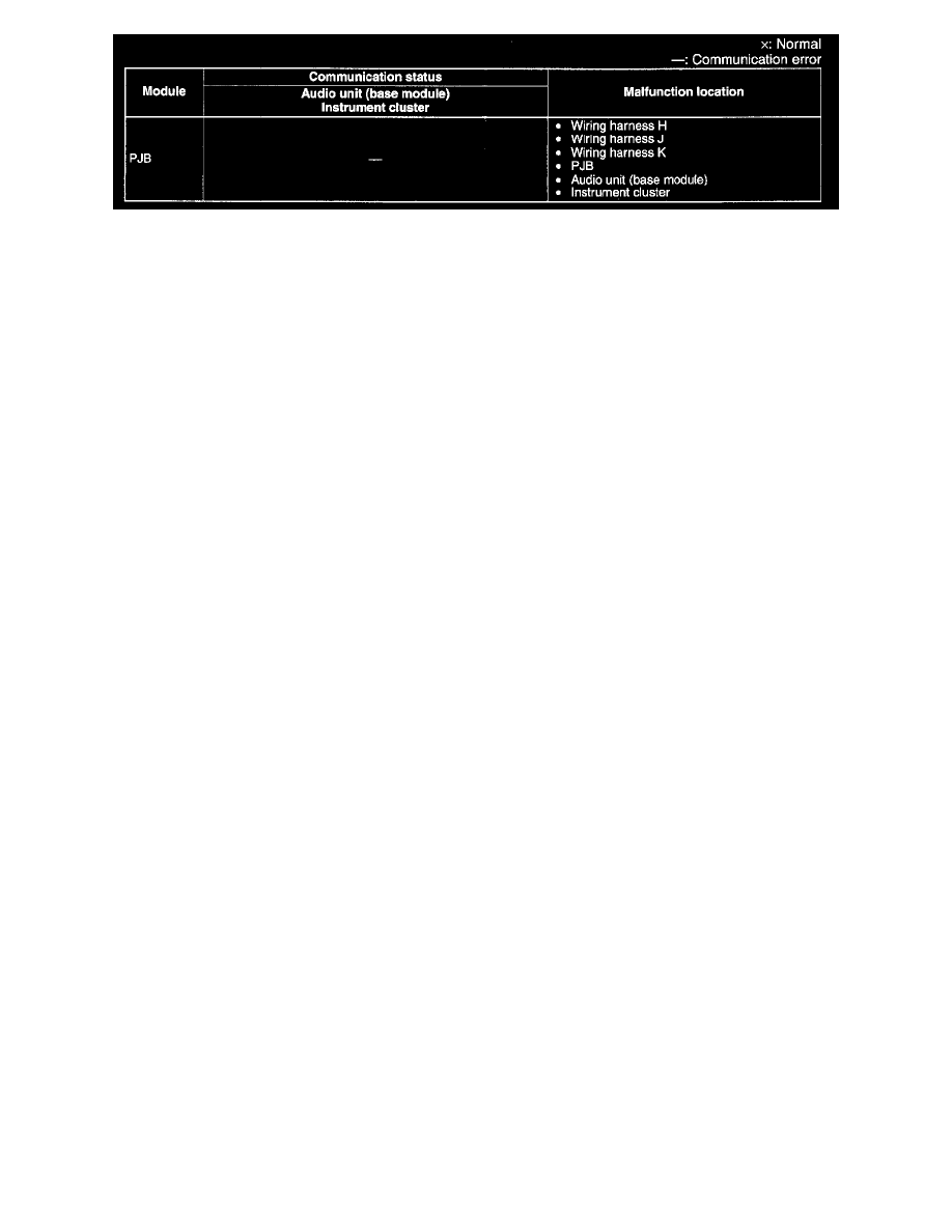
2. Referring to the table, determine the malfunctioning part of the CAN system.
Repair Procedure
1. Inspect the connector of malfunctioning module.
-
If there is any malfunction, repair or replace the connector.
2. Inspect the malfunctioning wiring harnesses as follow:
-
If there is any malfunction, repair or replace the wiring harnesses.
-
If there is no malfunction, replace the malfunctioning module.
-
Short to GND
-
Short to power supply
-
Twisted pair short each other
-
Open circuit
3. Make sure to reconnect all disconnected connectors.
4. Clear the CAN system related DTCs using the WDS or equivalent.
5. Verify if the CAN system related DTCs are displayed using the WDS or equivalent.
-
If the same following DTCs are present, replace the malfunctioning module.
-
U0073 (PCM, EHPAS control module, instrument cluster, SAS control module)
-
U0516 (TPMS control module)
-
U1900(PJB)
-
U2012 (ABS HU/CM)
-
U2516 (Instrument cluster)
-
If other DTC is present, perform the appropriate DTC inspection. (See DTC TABLE [MULTIPLEX COMMUNICATION SYSTEM].) See:
Testing and Inspection/Diagnostic Trouble Code Descriptions