
6 L4-2.5L (2010)
Variable Valve Timing Actuator: Testing and Inspection
VARIABLE VALVE TIMING ACTUATOR INSPECTION [L5]
CAUTION:
-
Variable valve timing actuator can not be disassembled because it is a precision unit.
1. Disconnect the negative battery cable.
2. Remove the plug hole plate. See: Service and Repair/Removal and Replacement/Plug Hole Plate Removal/Installation
3. Remove the ignition coils. See: Powertrain Management/Ignition System/Ignition Coil/Service and Repair
4. Remove the ventilation hose. See: Intake Manifold/Service and Repair
5. Disconnect the camshaft position (CMP) sensor connector.
6. Disconnect the oil control valve (OCV) connector.
7. Remove the cylinder head cover. See: Timing Components/Timing Chain/Service and Repair
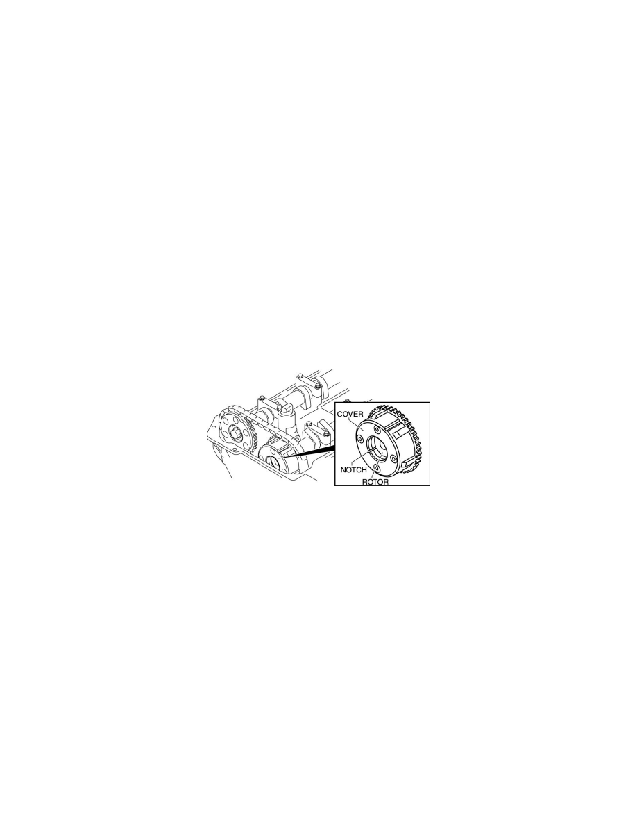
8. Confirm that notch of the rotor and notch of the cover at the variable valve timing actuator are aligned and fitted.
-
If the notch of the rotor and notch of the cover are not aligned, turn the crankshaft clockwise two rotations. Verify that notch of the rotor and
notch of the cover are aligned.
-
If the both notches are still not aligned, replace the variable valve timing actuator.
-
If, when turning the crankshaft, there is a hitting noise from the variable valve timing actuator each time the cam passes the fully lifted
position, it means that the actuator is not secured. Replace the actuator.
9. Install the cylinder head cover. See: Timing Components/Timing Chain/Service and Repair
10. Connect the OCV connector.
11. Connect the CMP sensor connector.
12. Install the ventilation hose. See: Intake Manifold/Service and Repair
13. Install the ignition coils. See: Powertrain Management/Ignition System/Ignition Coil/Service and Repair
14. Install the plug hole plate. See: Service and Repair/Removal and Replacement/Plug Hole Plate Removal/Installation
15. Connect the negative battery cable.