
6 L4-2.5L (2010)
Blind Spot Module: Component Tests and General Diagnostics
BLIND SPOT MONITORING (BSM) CONTROL MODULE INSPECTION
1. Remove the trunk end trim. See: Body and Frame/Interior Moulding / Trim/Scuff Plate/Service and Repair/Trunk End Trim Removal/Installation
2. Remove the rear seat cushion. See: Body and Frame/Seats/Seat Cushion/Service and Repair/Rear Seat Cushion Removal/Installation
3. Remove the rear side seat back. See: Body and Frame/Seats/Service and Repair/Overhaul/Rear Side Seat Back Removal/Installation
4. Remove the trunk side trim.
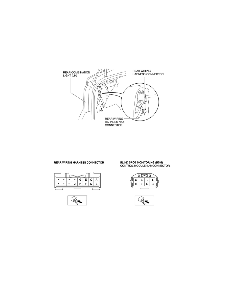
5. Measure the BSM control module terminal voltage using the rear wiring harness connector in the position shown in the figure.
Terminal Voltage Table (Reference)
NOTE:
-
The BSM control module connector cannot be connected to a tester due to its water-resistance processing, therefore the rear wiring harness
connector is used for measuring the terminal voltage.
BSM control module (LH)