
6 V6-3.0L (2007)
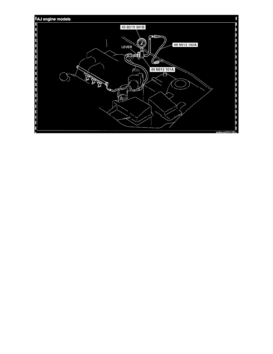
5. Turn the SST lever so that it is 90° to the hose as shown in the figure.
6. Push the SST quick release connector into the fuel pipe until a click is heard.
7. Install the battery and battery tray. (AJ)
8. Connect the negative battery cable.
CAUTION: Connecting to the wrong check connector terminal may cause malfunction. Carefully connect only to the specified terminal.
9. Short the check connector terminal F/P to body GND using a jumper wire.
10. Turn the ignition switch to the ON position to operate the fuel pump.
11. Turn the ignition switch to the LOCK position.
12. Measure the fuel pump hold pressure after 5 min.
-
If not as specified, replace the fuel pump after inspecting the following:
-
Fuel line for clogging or leakage
Fuel pump hold pressure
L3: More than 200 kPa {2.0 kgf/sq.cm, 29 psi)
AJ: More than 250 kPa {2.5 kgf/sq.cm, 36 psi)
13. Disconnect the jumper wire.
14. Complete the "BEFORE REPAIR PROCEDURE". (See BEFORE REPAIR PROCEDURE[L3, AJ].) See: Powertrain Management/Fuel Delivery
and Air Induction/Service and Repair/Procedures/Before Repair Procedure
15. Disconnect the negative battery cable.
16. Remove the battery and battery tray. (AJ)
17. Disconnect the SST.
NOTE: A checker tab is integrated with the quick release connector for new plastic fuel hoses. The checker tab will be released from the quick
release connector after it is completely engaged with the fuel pipe.
18. Inspect the plastic fuel hose and fuel pipe sealing surface for damage and deformation, and replace if necessary.
-
If the quick release connector 0-ring is damaged or has slipped, replace the plastic fuel hose.
19. Apply a small amount of clean engine oil to the sealing surface of the fuel pipe.
20. Reconnect the plastic fuel hose straight to the fuel pipe until a click is heard.
21. Lightly pull and push the quick release connector a few times by hand and verify that it can move 2.0-3.0 mm {0.08-0.11 in} and it is connected
securely.
-
If quick release connector does not move at all, verify that 0-ring is not damaged or slipped, and reconnect the quick release connector.
22. Complete the "AFTER REPAIR PROCEDURE". (See AFTER REPAIR PROCEDURE[L3, AJ].) See: Powertrain Management/Fuel Delivery
and Air Induction/Service and Repair/Procedures/After Repair Procedure