
626 L4-1998 cc 2.0L SOHC Turbo FE (1986)
Throttle Position Sensor: Testing and Inspection
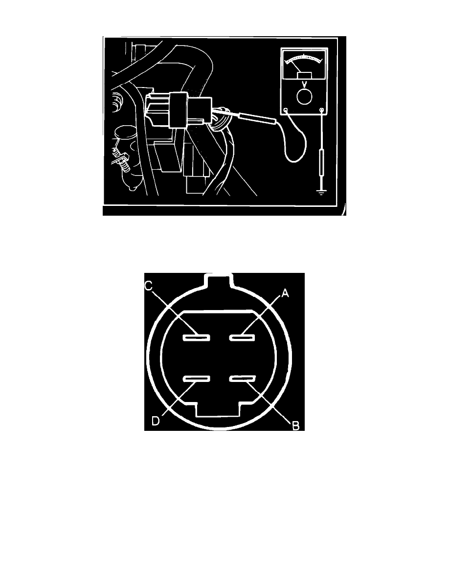
Fig. 5 Checking Throttle Sensor Terminal Voltage
TERMINAL VOLTAGE
1.
Remove rubber boot from connector Fig. 5.
2.
Turn ignition switch on.
Fig. 74 Throttle sensor connector terminal identification. Turbo
3.
Check voltage between each terminal and ground, then open throttle valve and check voltage between each terminal and ground, Fig. 74. Voltage
should be .4---.6 volt at terminal A with throttle valve closed, approximately 4.5 volts at terminal A with throttle valve open, less than 1.5 volts at
terminal B regardless of throttle valve position, 4.5---5.5 volts at terminal C regardless of throttle valve position, less than 1.5 volts at terminal D
with throttle valve closed and approximately 12 volts at terminal D with throttle valve open.
4.
If voltage is incorrect at terminal D only, check throttle sensor setting.
5.
If voltage is incorrect at terminals other than D, check resistances of throttle sensor, terminals 2A, 2C, 2E and 1G of EGI control unit and the
wiring harness.
6.
Install rubber boot to connector.