
626 L4-1998 cc 2.0L SOHC Turbo FE (1986)
Steering Angle Sensor: Testing and Inspection
1.
Disconnect AAS control unit electrical connector, then place ignition switch in On position.
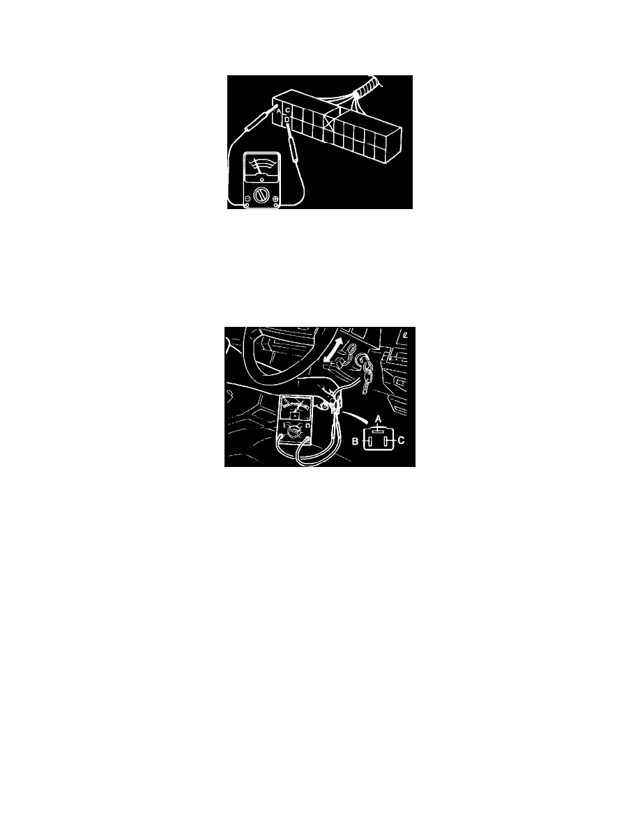
Fig. 22 Angle sensor circuit test. 1986-87
2.
Connect suitable ohmmeter to terminals A and D, Fig. 22. With steering wheel in neutral position, meter should indicate approximately 25k ohms.
Gradually turn steering wheel 180° clockwise, meter should increase from 25k ohms to 50k ohms. Turn steering wheel back to neutral position,
then gradually turn wheel 180° counterclockwise, meter should increase from 25k ohms to 50k ohms.
3.
Connect ohmmeter to terminals C and D, Fig. 22. With steering wheel in neutral position, meter should indicate 50k ohms.
4.
If resistance is not as specified in steps 2 and 3, check for broken wire in harness, repair as required.
5.
Remove steering column cover, then disconnect angle sensor electrical connector
Fig. 23 Angle sensor component test. 1986-87
6.
Connect suitable ohmmeter to terminals B and C, Fig. 23. With steering wheel in neutral position, meter should indicate approximately 25k ohms.
Gradually turn steering wheel 180° clockwise, meter should increase from 25k ohms to 50k ohms. Turn steering wheel back to neutral position,
then gradually turn wheel 180° counterclockwise, meter should increase from 25k ohms to 200k ohms.
7.
Connect ohmmeter to terminals A and C, Fig. 23. With steering wheel in neutral position, meter should indicate 50k ohms.
8.
If resistance is not as specified in steps 6 and 7, place steering wheel in neutral position, then align angle sensor matching marks.