
626 L4-2.0L DSL (1984)
Radiator Cooling Fan Motor: Testing and Inspection
FAN MOTOR
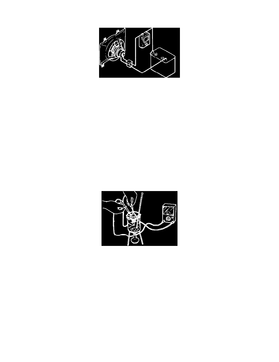
Fig. 1 Fan motor test. 1984-85 GLC, 1984-88 626, & 1986-87 323, 1986-88 RX-7, 1988 MX-6 & 1988 323 w/2 wheel drive
1.
Connect a 12 volt power source and an ammeter to fan motor, Fig. 1.
2.
Ensure motor turns freely at less than number of amps specified:
a. 1984 626, 9.5.
b. 1984-85 GLC, 6.7-8.7.
c. 1985-87 626 and 1988 626 and MX-6 turbo models w/automatic transaxle, 8-11.
d. 1986-87 323 models, 6.1-7.3.
e. 1986-88 RX-7, 2.4-2.6.
f.
1988 626 & MX-6 models w/manual transaxle, 323 sedan models w/single overhead cam engine and manual transaxle and 323 station
wagon, 5.6-7.6.
g. 1988 626 & MX-6 turbo models w/automatic transaxle, 10.6-16.6.
h. 1988 323 sedan models w/single overhead cam engine and automatic transaxle and 323 sedan models w/double overhead cam engine, 10-11.
3.
Replace motor if operation is not as described.
FAN RELAY
1.
Disconnect water temperature switch electrical connector and turn ignition switch to the On position.
2.
If fan does not rotate, inspect fan relay and motor electrical connections and condition of corresponding fuse and repair or replace as necessary.
WATER TEMPERATURE SWITCH
Fig. 7 Water temperature switch test. 1984-85 GLC, 1984-88 626, 1986-88 RX-7 & 323 & 1988 MX-6
1.
Remove water temperature switch from vehicle and place in a suitable container of water. Do not disconnect water temperature switch with
ignition switch On, as the fan motor will be energized.
2.
Using an ohmmeter, Fig. 7, ensure no continuity exists above 196 degrees F on 1984-85 GLC models or 207 degrees F on all other models. When
temperature is lowered to below 183 degrees F on 1984-85 GLC models or 194 degrees F on all other models, continuity should be indicated.
When installing water temperature switch, use a new O-ring and ensure no water leaks from the switch. Do not use sealing tape on switch
threads.