
626 L4-2184cc 2.2L SOHC Turbo F2 (1988)
Constant Velocity Joint Boot: Service and Repair
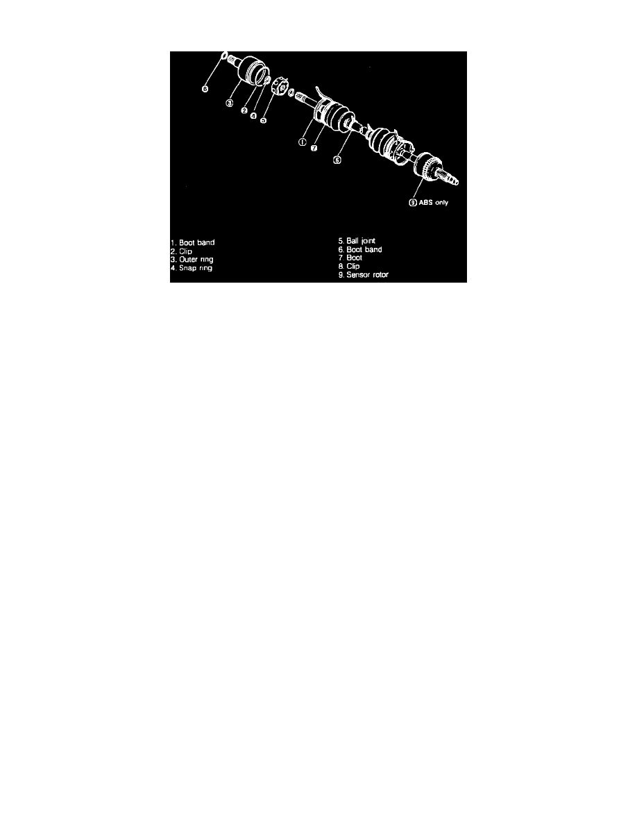
Fig. 14 Exploded view of driveshaft. 1988 626 & MX-6 w/manual transaxle
Disassembly, Models W/Manual Transaxle
Disassemble driveshaft in numerical order, Fig. 14, noting the following:
1.
Clamp shaft in vise, using protectors in vise to avoid damage.
2.
Do not allow dirt or foreign matter in joint during disassembly or assembly.
3.
Do not disassemble ball joint at wheel side and do not wipe grease off unless necessary.
4.
Do not remove clip used to secure outer ring to ball joint at differential side unless necessary. If clip is removed, do not reuse.
5.
Paint alignment marks on driveshaft and outer ring, then remove clip with flat tipped screwdriver.
6.
Place alignment marks on driveshaft end and inner ring, then remove snap ring with snap ring pliers.
7.
Disassemble balls, inner ring and cage as follows:
a. Paint alignment marks on inner ring and cage.
b. Turn cage approximately 30°, then pull it away from inner ring.
8.
Before removing boot, wrap shaft splines with tape.
Inspection, Models W/Manual Transaxle
1.
Check for twisted, bent or damaged shaft, replacing as necessary.
2.
Check for worn or scored splines, replacing as necessary.
3.
Check for worn, rusted or damaged outer ring, replacing as necessary.
Assembly, Models W/Manual Transaxle
Reverse disassembly procedure to assemble, noting the following:
1.
Wrap shaft splines with tape before installing boot. Wheel side and differential side boots are different, do not intermix.
2.
Fill inside of ball joint with grease supplied in kit.
3.
Securely fit boot to shaft and the outer race boot grooves.
4.
Align matching marks on inner ring and cage and install balls, then apply molybdenum disulfide grease to joint.
5.
Tighten boot band as follows. Use new band. Fold band in direction opposite forward rotation of driveshaft.
a. Fold band back by pulling on end of band.
b. Bend locking clip to lock end of band.