
626 ES V6-2.5L DOHC (1997)
General Module: Testing and Inspection
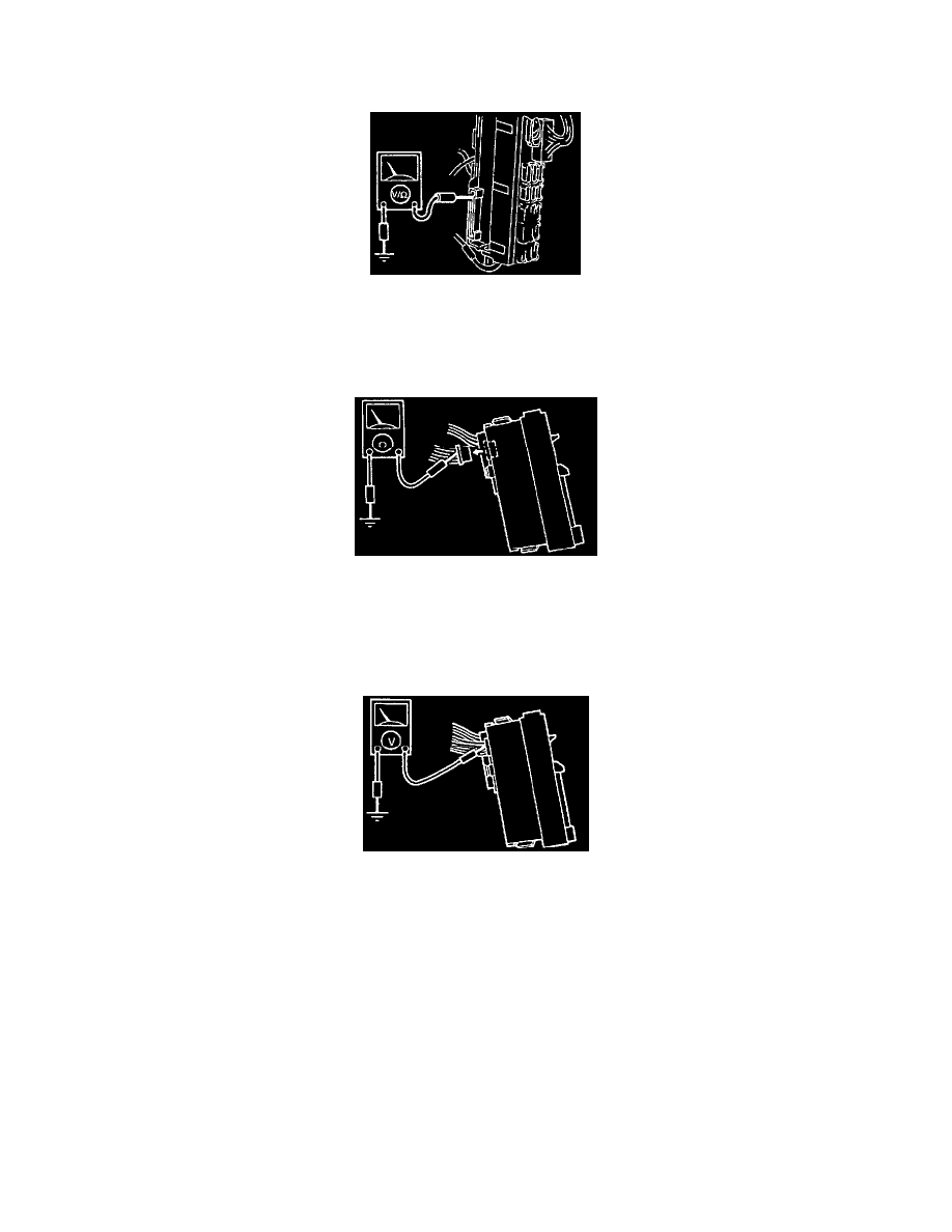
Inspection
Connector A
1. Remove the CPU from the joint box.
2. Measure the voltage at the CPU terminals from the joint box side, referring to the terminal voltage list below.
3. If not as specified, inspect the parts listed under "Inspection area" and the related wiring harnesses.
4. If the parts and wiring harnesses are OK but the system still does not work properly, replace the CPU.
Connector B
1. Follow the appropriate procedure, referring to the terminal voltage list below.
Terminals 2H (MX-6 only), 2N, and 2T
1. Disconnect the CPU connector.
2. Check for continuity between the terminals of the CPU connector and ground.
Terminals except 2H (MX-6 only), 2N, and 2T
1. Reconnect the CPU connector.
2. Install the CPU onto the joint box.
3. Measure the voltage at the CPU terminals.
2. If not as specified, inspect the parts listed under "Inspection area" and the related wiring harnesses.
3. If the parts and wiring harnesses are OK but the system still does not work properly, replace the CPU.