
B3000 V6-3.0L (2007)
4. Tighten the servo rod selecting gauge adjusting SST screw.
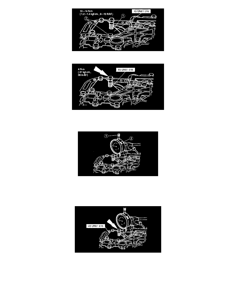
5. Install dial indicator with bracketry on the transmission case.
(1) Position the indicator on the piston pad.
(2) Set the dial indicator to zero.
Note:
^
If the piston travel in this step is 3-5.6 mm (0.120-0.220 in), it is within specification. If the piston travel is greater than 5.6 mm (0.220
in), use the next longer piston and rod. If the piston travel is less than 3mm (0.120 in), use the next shorter piston and rod.
6. Back out the servo gauge adjusting screw until it bottoms out on the tool. Record the distance the servo piston traveled.
Caution:
^
Make sure the test spring is removed after this step.
7. Use the above procedure to check the piston travel with the newly selected reverse band servo piston and rod (if required) to make sure that the
piston travel is 3-5.6 mm (0.120-0.220 in). Remove the servo gauge and the reverse band servo return spring.
^
Grooves are located on reverse servo rod.