
B3000 SE Regular Cab 4WD V6-3.0L OHV (1998)
^
HO2S Switching Rate: Do not attempt to compare HO2S switching rates from bank to bank or vehicle to vehicle. Because of the adaptive strategy of
the PCM, the switching rates are constantly adapting to; customer driving habits, engine and component wear, and engine operating conditions.
^
When removing an HO2S: Always use a 22 mm wrench, when installing an HO2S always use a crows foot and torque wrench and tighten it to 30 +/-
4 lb.-ft. (41 +/- 5 Nm).
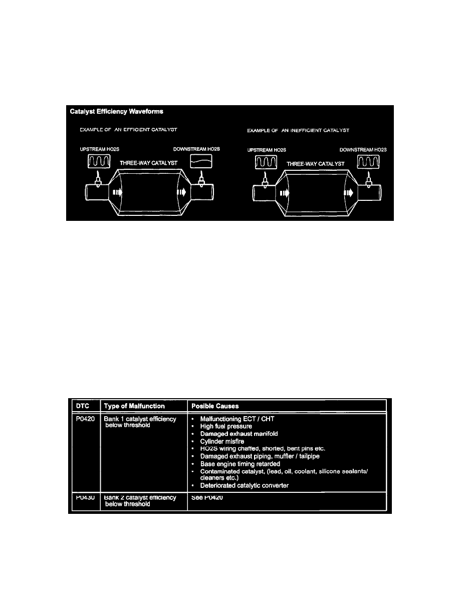
Catalyst Efficiency Monitor Description
CATALYST EFFICIENCY MONITOR DESCRIPTION
This monitor checks for deterioration of the catalytic converter by comparing upstream (front) and downstream (rear) oxygen sensor readings. When the
signal from the downstream oxygen sensor is similar to the signal from the upstream oxygen sensor, the PCM judges that the catalytic converter has
deteriorated which illuminates the MIL and stores a DTC. Under normal closed loop engine operation with a good catalytic converter, the oxygen
storage capacity of the catalyst is high, so the voltage of the rear HO2S will switch slowly. With a deteriorated catalytic converter, the rear HO2S will
fluctuate rapidly near the same frequency of the front HO2S. Refer to the Illustration showing an efficient catalyst and a deteriorated catalyst.
The efficient catalyst on the left has a switch rate or several inversions across the 0.45 volt threshold on the front HO2S while the rear HO2S has few
inversions across 0.45 volts. The inefficient catalyst on the right has the same number of inversions on both the front and rear HO2S.
^
Counting Switches: Front and rear HO2S switches (switches past 0.45 volts from rich to lean) are counted. After the required number of front
switches are counted, the front to rear switch ratio is calculated. A new or efficient catalytic converter will have a switch ratio near 0, while a failed
catalytic converter will have a switch ratio of 0.8 to 0.9.
^
OBDII Drive Cycles: A moving average is used to judge catalytic converter condition, so it may take up to six OBD-II drive cycles for the MIL to
illuminate for a deteriorated catalytic converter.
^
Conditions: This monitor only runs after the following conditions are met: the engine is at normal operating temperature based on good inputs from
the ECT or CHT, ambient air temperature is not extreme (based on IAT), the engine is operating at greater than minimum load (based on MAF),
vehicle speed is within a specific window (based on VSS), and the vehicle is driven at part throttle acceleration (based on TPS).
Catalyst Efficiency Monitor DTC's
Catalyst Efficiency Monitor Service Tips
^
Switch Ratio: A properly operating front HO2S will have a high switch rate in normal closed loop. With an efficient catalytic converter, the
down-stream HO2S will have a low switch rate. The switch ratio is determined by the PCM dividing the number of down-stream switches by the