
B3000 SE Regular Cab 4WD V6-3.0L OHV (1998)
Starter Motor: Testing and Inspection
STARTING SYSTEM INSPECTION
WARNING:
- When servicing the starter motor or performing other under hood work in the vicinity of the starter motor, be aware that the heavy
gauge battery input lead at the starter solenoid is "electrically hot" at all times.
CAUTION:
- A protective cap or boot is provided over the battery input terminal on all vehicle lines and must be replaced after servicing. Be sure to
disconnect the battery ground cable before servicing the starter motor.
NOTE:
- Always make the Multimeter connections at the component terminal rather than at the wiring end connector. Making a connection at the wiring
end connector could result in false readings because the meter will not pick up a high resistance between the wiring connector and the component.
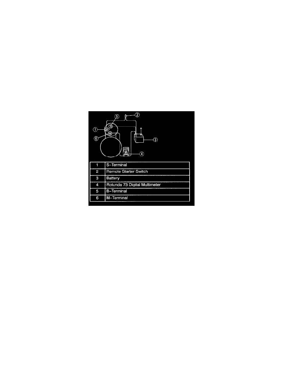
Starter Motor - Feed Circuit
1. Make sure the battery is fully charged.
2. Disconnect the fuel pump shutoff switch.
3. Connect a remote starter switch between the starter solenoid S-terminal and the battery positive (+) terminal.
4. Connect the Multimeter positive lead to the battery positive (+) post. Connect negative lead to the starter solenoid M-terminal.
5. Engage the remote starter switch. Read and record the voltage. The voltage reading should be 0.5 volts or less.
6. If the voltage reading is 0.5 volts or less, go to the Starter Motor-Ground Circuit Component Test.
7. If the voltage reading is greater than 0.5 volts, indicating excessive resistance, move the Digital Multimeter negative lead to the starter solenoid
B-terminal and repeat the test. If the voltage reading at the B-terminal is lower than 0.5 volts, the concern is either in the connections at the starter
solenoid or in the solenoid contacts.
8. Remove the cables from solenoid B-, S- and M-terminals. Clean the cables and connections and reinstall the cables to the proper terminals. Repeat
Steps 3 through 6. If the voltage drop reading is still greater than 0.5 volts when checked at the M-terminal or less than 0.5 volts when checked at
the B-terminal, the concern is in the solenoid contacts. Replace the starter motor.
9. If the voltage reading taken at the solenoid B-terminal is still greater than 0.5 volts after cleaning the cables and connections at the solenoid, the
concern is either in the positive (+) battery cable connection or in the positive battery cable.
10. By moving the Digital Multimeter toward the battery and checking each mechanical connection point, the excessive voltage drop can be located.
When the high reading disappears, the last mechanical point that was checked is the concern. Repair or replace this connection as required.
Starter Motor-Ground Circuit
A slow cranking condition can be caused by resistance in the ground or return portion of the cranking circuit. Check the voltage drop in the ground
circuit as follows:
1. Disconnect the idle adjusting screw.
2. Connect a remote starter switch between the starter solenoid S-terminal and the battery positive (+) terminal.
3. Connect the multimeter positive lead to the starter motor housing (the connection must be clean and free of rust or grease). Connect the negative
lead to the negative (-) battery terminal.
4. Engage the remote starter switch and crank the engine. Read and record the voltage reading. The reading should be 0.2 volts or less.
5. If the voltage drop is more than 0.2 volts, clean the negative cable connections at the battery and body connections, and retest.
6. If the voltage drop is greater than 0.2 volts, determine which way the current is flowing in the cable. Connect the multimeter positive lead to the
end of the cable nearest battery positive.