mazda Workshop Repair Guides

Mazda Workshop Service and Repair Manuals

Sensors and Switches - Computers and Control Systems > < Feedback Control Unit <--> [Engine Control Module]|Locations|Page 827
Page 3
background image

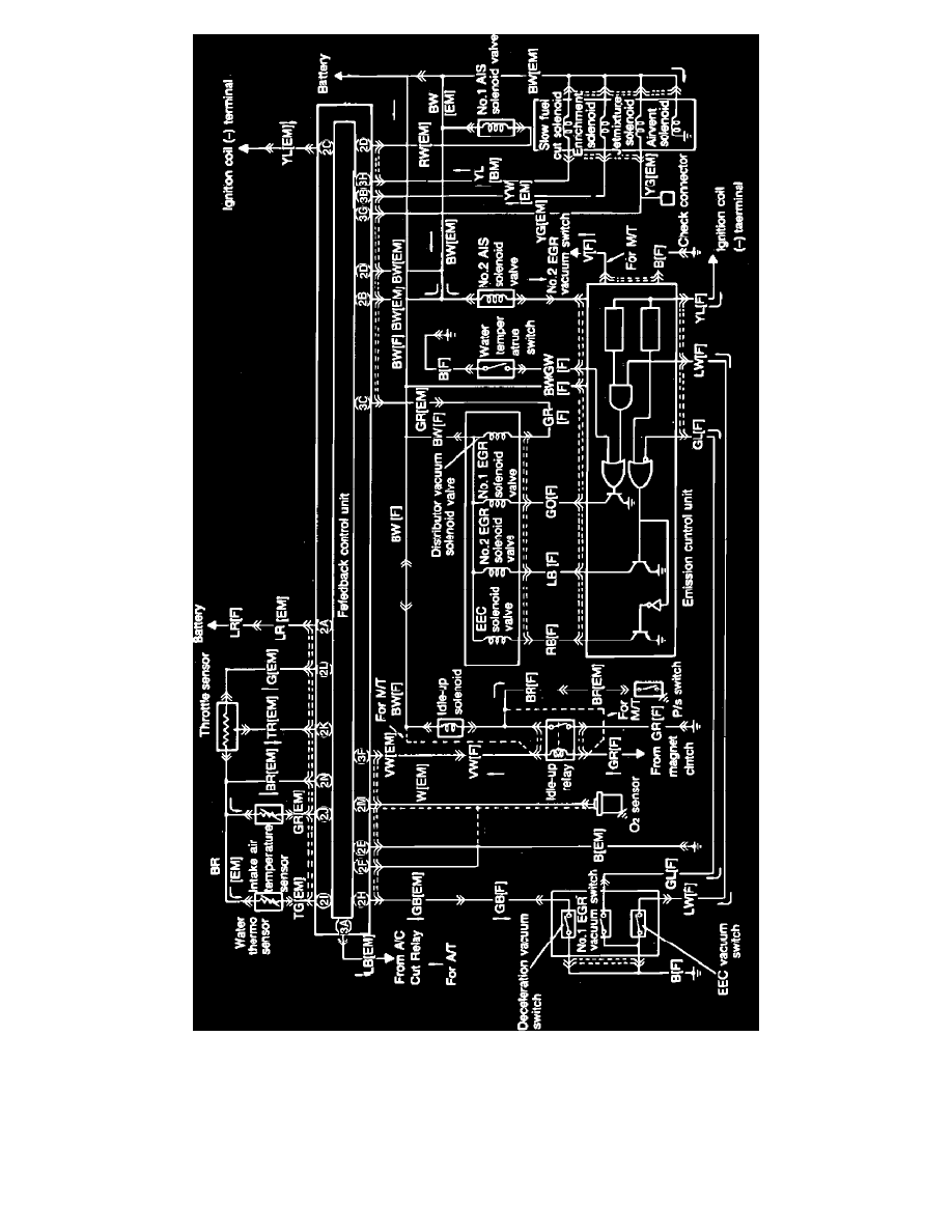
Fig. 9 Feedback control system wiring diagram.

4.

Refer to Fig. 9 for terminal locations.

5.

If specified voltage is not obtained, check wiring, electrical connectors and related component(s) and correct as necessary.

Sensors and Switches - Computers and Control Systems > < Feedback Control Unit <--> [Engine Control Module]|Locations|Page 827