
MPV DX V6-2.5L DOHC (2000)
EGR Boost Sensor: Testing and Inspection
Using the SST (NGS Tester)
NOTE: Perform the following test only when directed.
1. Turn the ignition switch to ON.
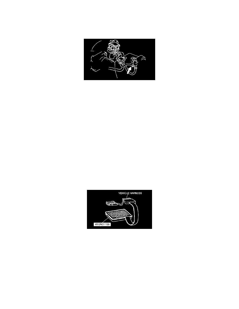
2. Disconnect the vacuum hose between the EGR boost sensor and the EGR boost sensor solenoid valve.
3. Set the NGS tester and monitor the BARO V PID.
4. Verify that the BARO V PID is within the specification.
NOTE:
-
The output voltage varies with the following condition.
-
Input voltage 4.5 - 5.5 V
-
Outside temperature 10 - 50 °C {50 - 122 °F}
-
Sea level -200 - 3,000 m {-656 - 9,840 ft}
Specification
BARO V: 2.3 - 4.7 V
CAUTION: Do not apply vacuum more than specified. Doing so will damage the EGR boost sensor.
5. Apply the vacuum of -26.6 kPa {-200 mmHg, -7.85 inHg} to EGR boost sensor and verify that the BARO V PID varies from Step 4 as specified.
-
If not as specified, perform the "Circuit Open/Short Inspection".
Specification
BARO V variation: 0.8 - 1.3 V
Circuit Open/Short Inspection
1. Disconnect the PCM connector.
2. Connect the SST (104 Pin Breakout Box) with the PCM disconnected.
3. Tighten the connector attaching bolt.
Tightening torque
7.9 - 10.7 N.m {80 - 110 kgf.cm, 69.5 - 95.4 in.lbf}
4. Disconnect EGR boost sensor connector.
5. Inspect the following wiring harness for open or short (Continuity check).
Open circuit
-
If there is no continuity, the circuit is open. Repair or replace the harness.
-
EGR boost sensor terminal C (harness-side) and 104 pin breakout box terminal 90
-
EGR boost sensor terminal B (harness-side) and 104 pin breakout box terminal 34
-
EGR boost sensor terminal A (harness-side) and 104 pin breakout box terminal 91