
MPV LX 2WD V6-3.0L SOHC (1998)
Central Control Module: Diagram Information and Instructions
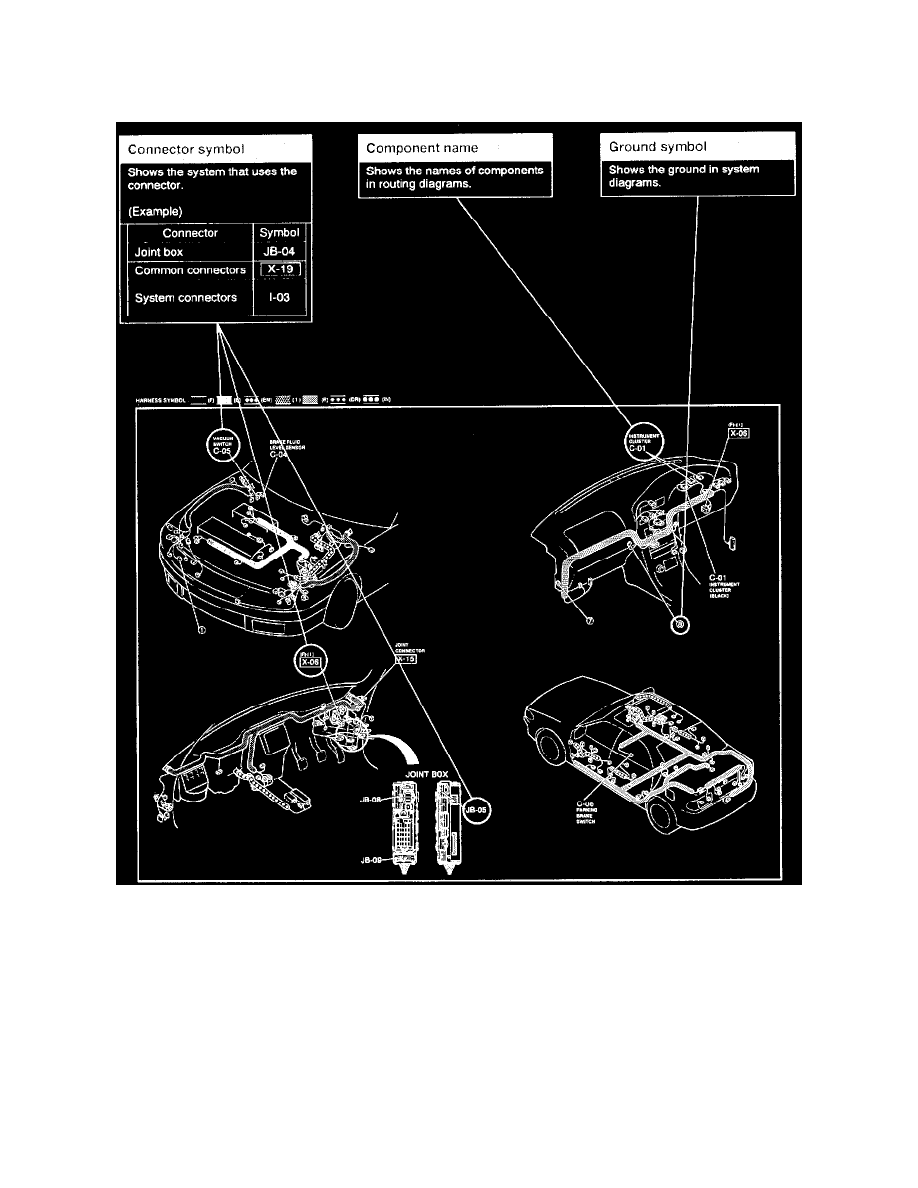
Routing Diagram
Routing Diagram
^
The routing diagram shows where electrical components are on the system circuit diagram by call out line and connector symbols.
Harness Symbols
Description Of Harness ........................................................................................................................................................................................... Symbol
Front Harness ..................................................................................................................................................................................................................... (F)
Front No.2 Harness .......................................................................................................................................................................................................... (F2)
Engine Harness .................................................................................................................................................................................................................. (E)
Dash Harness ..................................................................................................................................................................................................................... (D)
Rear Harness ...................................................................................................................................................................................................................... (R)
Rear No.2 Harness ........................................................................................................................................................................................................... (R2)
Rear A Harness ............................................................................................................................................................................................................... (RA)
Instrument Panel Harness .................................................................................................................................................................................................... (I)