
MX-3 L4-1598cc 1.6L DOHC (1995)
A/C (Switch) Signal: Description and Operation
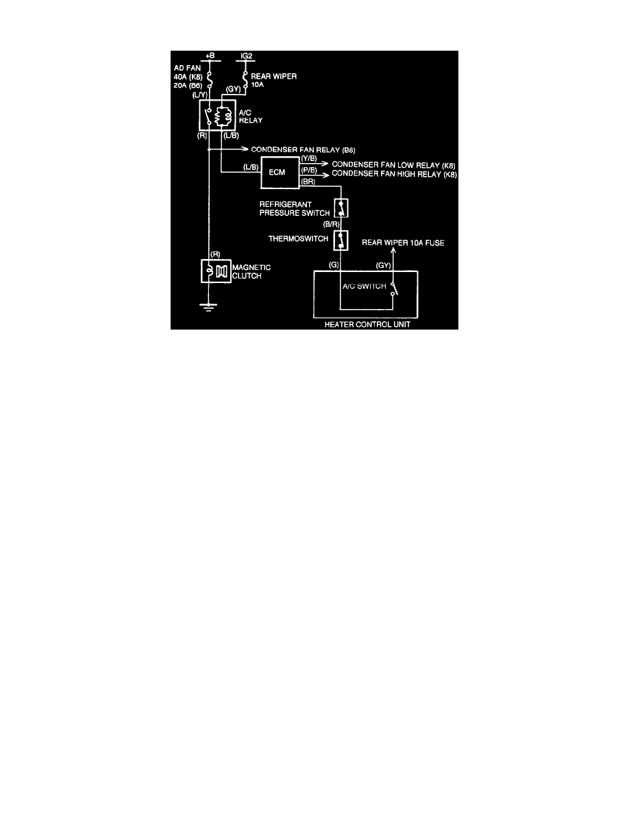
View: A/C Signal Path Diagram
PURPOSE
To provide the engine control module (ECM) with an input signal which corresponds with the A/C system (ON/OFF) demand from the heater A/C
control unit. The system design allows the ECM to control the actual ON/OFF operation of the magnetic clutch on the A/C compressor.
OPERATION
The A/C signal is not directly connected to the air conditioning system. The A/C signal tells the ECM, "Turn the A/C ON or OFF". When the
ECM receives the "A/C ON" signal, it (the ECM) determines if it should turn the A/C ON based on inputs from other systems and sensors such as;
-
A/C Cut-Off Control System
-
Engine Coolant Temperature Sensor
When the blower switch and the A/C switch are turned ON, power flows to ECM input terminal 1Q (BR wire). The ECM recognizes this signal as
a demand for A/C ON operation. The ECM will control the ON/OFF operation of the A/C system from this point via the ground circuit for the air
conditioner relay. The ground circuit for the A/C relay connects to ECM terminal 1J (L/B wire).