
MX-5 Miata L4-2.0L (2008)
Information Bus: Testing and Inspection
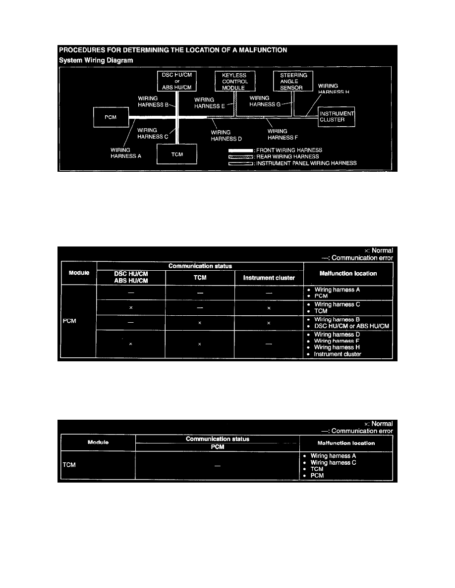
PROCEDURES FOR DETERMINING THE LOCATION OF A MALFUNCTION
System Wiring Diagram
System Wiring Diagram
PCM
1. Inspect the display of DTC U0101, U0121 and/or U0155, using the WDS or equivalent. (See DTC TABLE [MULTIPLEX COMMUNICATION
SYSTEM].) See: Testing and Inspection/Diagnostic Trouble Code Descriptions
2. Referring to the given table, determine the malfunctioning part of the CAN system.
TCM
1. Inspect the display of DTC U0100 using the WDS or equivalent. (See DTC TABLE [MULTIPLEX COMMUNICATION SYSTEM].) See:
Testing and Inspection/Diagnostic Trouble Code Descriptions
2. Referring to the given table, determine the malfunctioning part of the CAN system.
DSC HU/CM or ABS HU/CM
1. Inspect the display of DTC U0100 (DSC), U0101 (DSC), U0155 (DSC), U1900 and/or U2023, using the WDS or equivalent. (See DTC TABLE
[MULTIPLEX COMMUNICATION SYSTEM].) See: Testing and Inspection/Diagnostic Trouble Code Descriptions