
Protege L4-1.5L DOHC (1995)
ABS Main Relay: Testing and Inspection
1. Inspect fail-safe harness as follows:
a. Place ignition switch in Off position and disconnect ABS control unit connector, then place ignition switch in On position.
b. On models less Traction Control System (TCS), use a suitable jumper wire to connect control unit connector terminal 2J to ground, Fig. 122
.
c. On models with TCS, use a suitable jumper wire to connect control unit connector 2B to ground, Fig. 118.
d. Inspect fail-safe relay if warning light illuminates or relay does not click when control unit connector terminal is grounded.
e. On models less TCS, inspect fail-safe relay and harness between relay and ABS hydraulic unit if control unit connector terminal 1D, Fig. 116,
does not indicate battery voltage.
f.
On models with TCS, inspect fail-safe relay and harness between relay and ABS hydraulic unit if control unit connector terminal 2Z, Fig. 118
, does not indicate battery voltage.
2. Inspect fail-safe relay as follows:
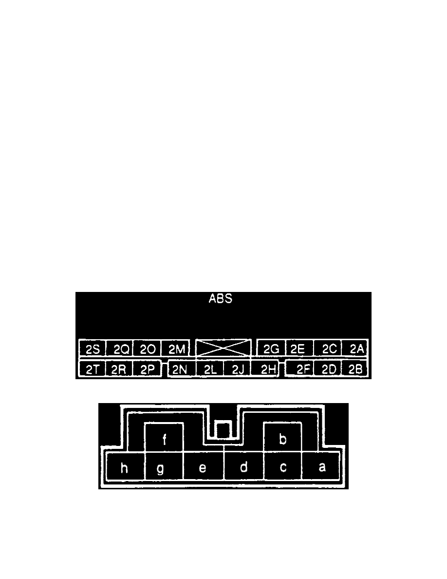
a. Measure resistance between ABS relay connector terminals c and d, Fig. 123. Resistance should be 60 - 100 ohms.
b. Check for continuity between terminals a and e, then between b and e, Fig. 123. Continuity should exist between a and e but not between b and
e.
c. Supply battery voltage between terminals d and c, then check again for continuity between terminals b and e and between a and e, Fig. 123.
Continuity should now exist between b and e but not between a and e.
d. If resistance or continuity is not as specified, replace ABS relay.
3. Inspect motor relay harness as follows:
a. Place ignition switch in Off position and disconnect ABS control unit connector, then place ignition switch in On position.
b. On models less TCS, connect terminals 2H and 2J, Fig. 122, to ground. Do not allow motor to operate longer than two seconds.
c. On models with TCS, connect terminals 2A and 2B, Fig. 118, to ground. Do not allow motor to operate longer than two seconds.
d. Inspect motor relay and harness between relay and ABS control unit if relay does not click when terminals are grounded.
e. Inspect motor relay, fuse and harness between relay and motor if motor does not operate.
4. Inspect motor relay as follows:
a. Measure resistance between ABS relay connector terminals e and h (or a and h), Fig. 123. Resistance should be 50 - 90 ohms.
b. Check for continuity between terminals b and f, Fig. 123. Continuity should not exist.
c. Supply battery voltage to terminals g and h, Fig. 123, then check continuity again between terminals b and f. Continuity should now exist.
d. Replace ABS relay if resistance or continuity is not as specified.
Fig. 122 ABS Control Unit Connector No. 2 Terminal Identification
Fig. 123 ABS Relay Connector Terminal Identification