
Protege L4-1839cc 1.8L DOHC (1990)
Igniter: Description and Operation
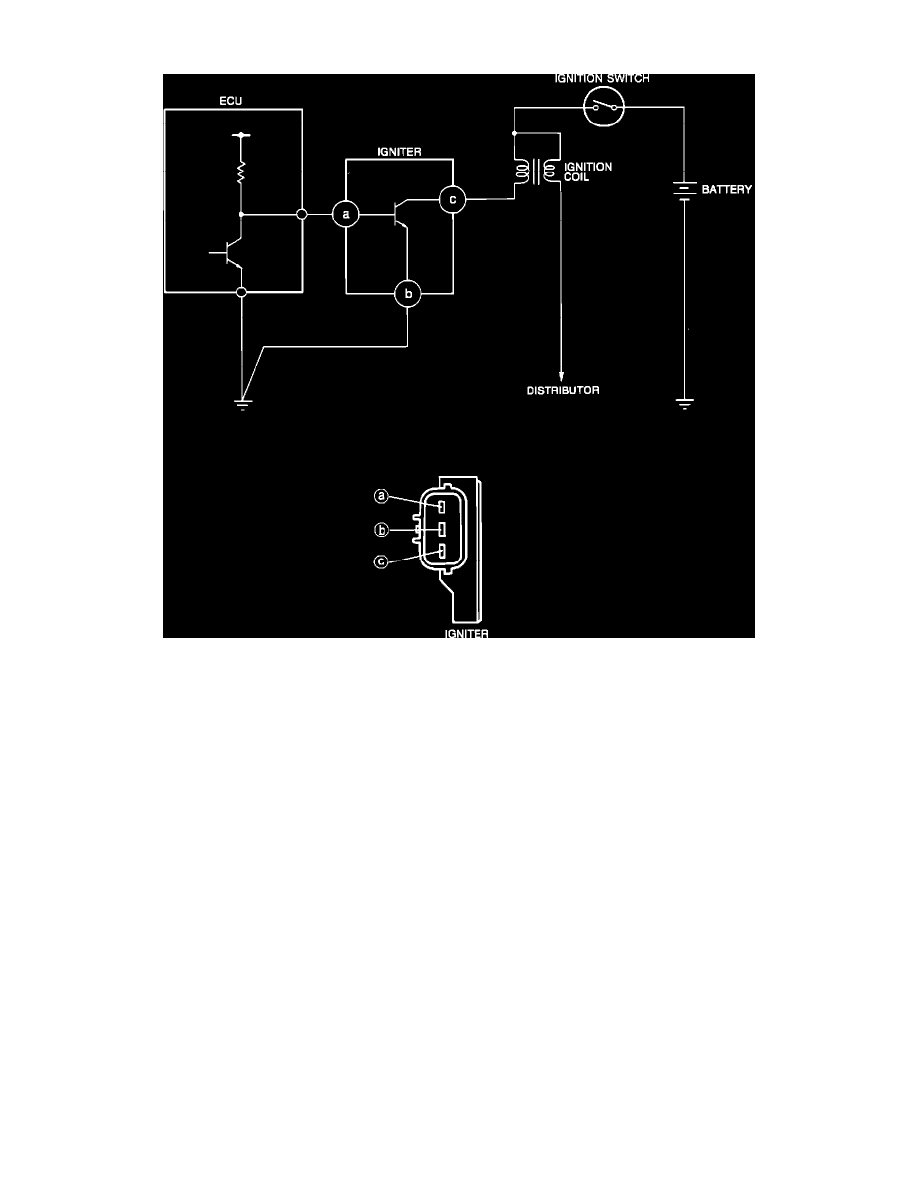
Igniter Circuit Diagram
The Igniter, located near the coil on the left side of the engine compartment, is a switching device that activates the primary ignition coil circuit. The
ECU determines optimum ignition timing from various inputs and transmits a primary current "OFF" signal to the igniter to control ignition timing.
The ECU calculates input from these devices to control ignition timing:
Distributor Ne signal
Water thermosensor
Airflow meter
Throttle sensor
Neutral and clutch switches (M/T)
Inhibitor switch (A/T)
Ignition switch ("START" position)
Diagnosis connector (for base timing adjustment)
EC-AT control unit