
Protege L4-1839cc 1.8L DOHC (1990)
Drive/Propeller Shaft: Service and Repair
Driveshaft
4 Wheel Drive
Fig. 1 Adjusting Propeller Shaft Height
1.
Raise and support vehicle.
2.
Scribe alignment marks on front and rear flanges.
3.
Remove front and rear propeller shaft attaching nuts.
4.
Remove center bearing support attaching nuts and washers.
5.
Remove center bearing support together with bushings, washers and shims, then the propeller shaft.
6.
Reverse procedure to install, noting the following:
a. Align match marks on companion flange of differential and yoke and install rear propeller shaft, torquing nuts to 20-22 ft. lbs.
b. Install center bearing support, torquing nuts to 27-38 ft. lbs.
c. Align match marks on companion flange of transfer unit and yoke, then install front propeller shaft, torquing nuts to 20-22 ft. lbs.
d. Check whether front and rear propeller shafts are aligned. If not, adjust height of center bearing support with shims, Fig. 1. Both shims must
be same thickness. Shims are available in following sizes; .0630 inch (1.6mm), .126 inch (3.2mm), .1772 inch (4.5mm), .2362 inch (6mm).
Removal & Installation
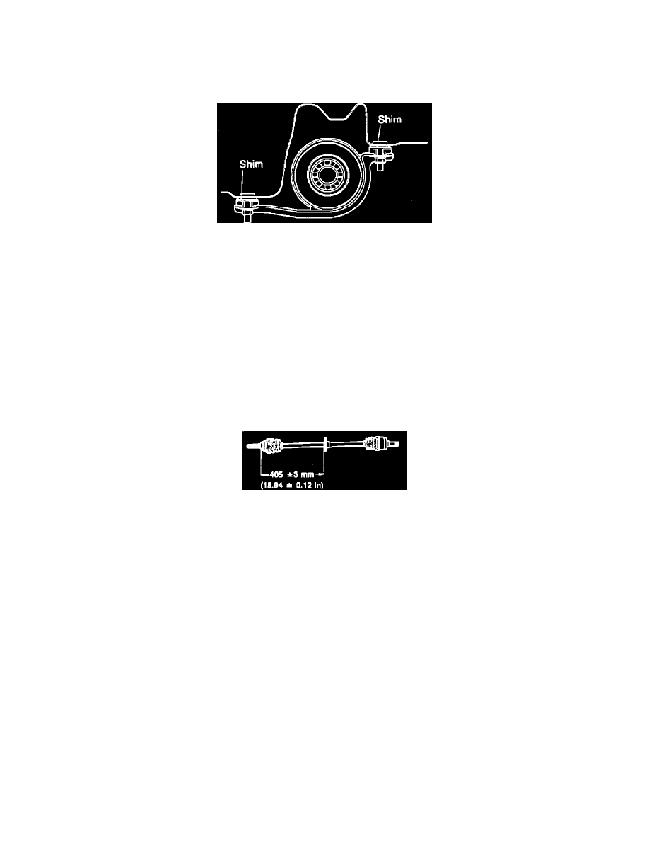
Fig. 1 Installed Position Of Dynamic Damper
1.
Raise and support vehicle and drain transaxle oil.
2.
Remove front wheels and the side covers.
3.
Apply brakes to lock hub, then raise nut tab and loosen but do not remove driveshaft locknut.
4.
On models with manual transaxle, remove stabilizer bar control link from lower arm.
5.
On all models, remove clamp bolt and nut.
6.
Pry down lower arm and disconnect ball joint. Be careful not to damage ball joint dust boot.
7.
On models with manual transaxle, separate driveshaft from transaxle by pulling hub outward, being careful not to use too much force at once. If
it is difficult to separate, insert a bar between driveshaft and transaxle case and lightly tap end of bar. Do not insert bar too far in between shaft
and case.
8.
On models with automatic transaxle, insert a bar between driveshaft and bearing housing and tap on end of bar. Do not insert bar too far in
between shaft and housing.
9.
On all models, remove driveshaft locknut and pull driveshaft out of wheel hub. Be especially careful not to damage oil seal.
10.
If driveshaft is stuck to front hub and cannot be removed, use tool 490839425C or equivalent to push shaft out.
11.
Pull driveshaft out of transaxle, then install differential side gear holder tool 49G030455 or equivalent to prevent entry of dirt or other foreign
matter.
12.
Reverse procedure to install, noting the following:
a. Ensure dynamic damper position is as shown, Fig. 1. When measuring distance, ensure ball joint is fully pushed toward driveshaft.
b. Before inserting driveshaft into transaxle, ensure oil seals are free of scratches. Install new clips on end of driveshaft and coat splines with
suitable grease.
c. When driveshaft and joint shaft are installed to transaxle, be careful not to damage oil seal. After installation, pull front hub outward and
ensure driveshaft does not disengage from transaxle.
d. Torque stabilizer bar control link nut to 9-13 ft. lbs., ensuring that there is .43 inch of thread exposed.
e. Install new driveshaft locknut and torque to 116-174 ft. lbs., then stake locknut, ensuring that it seats in groove in driveshaft. Do not stake
with pointed tool. Ensure wheel hub can be turned smoothly by hand.