
Protege DX L4-1489cc 1.5L DOHC MFI (1998)
Operation
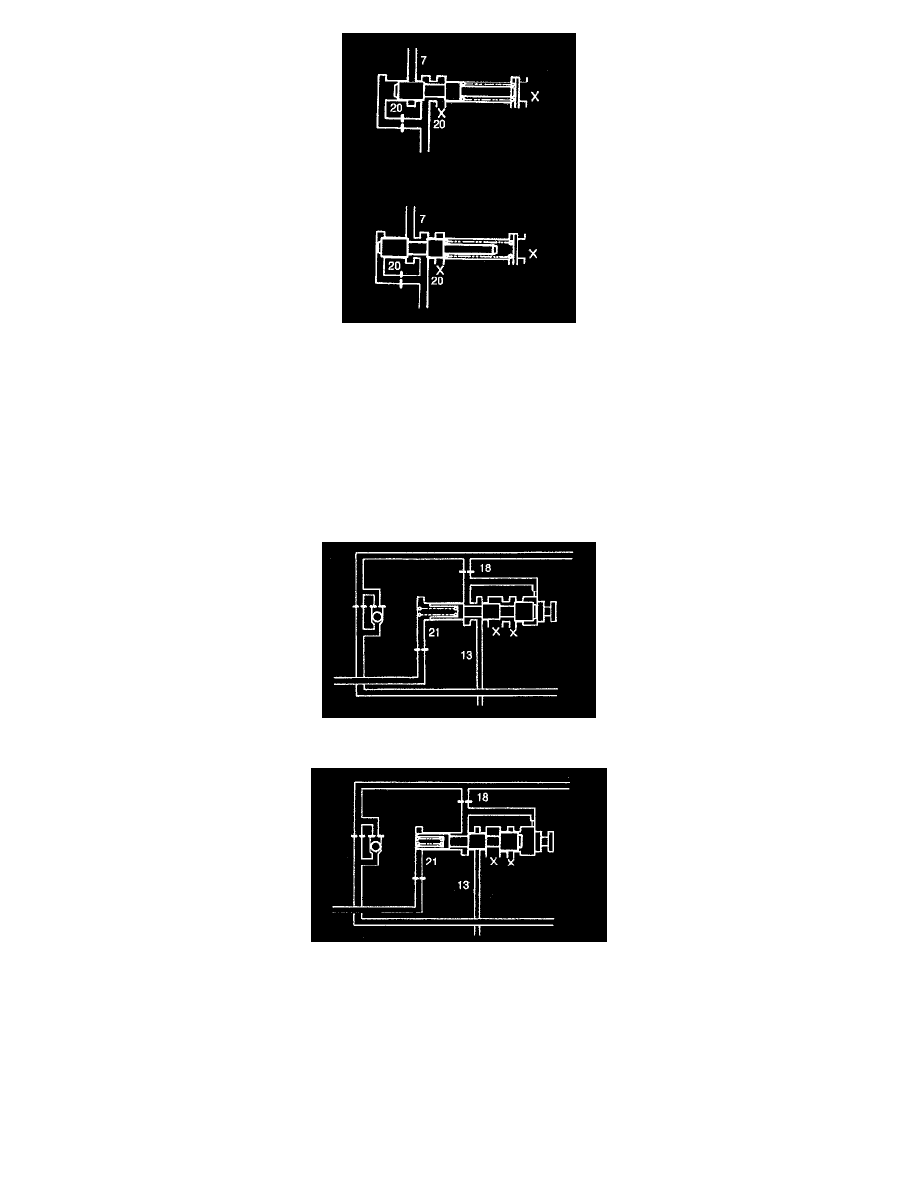
Solenoid reducing pressure (20) pushes the solenoid reducing valve to the right, while spring force pushes it to the left.
When solenoid reducing pressure (20) increases, the solenoid reducing valve moves to the right until pressure is drained.
This maintains a constant pressure to keep the spring force and line pressure (7) balanced. Solenoid reducing pressure becomes fixed.
Bypass Valve
Outline
The bypass valve controls the 3-4 clutch engagement timing and shift shock to match the throttle valve opening.
Operation
The bypass valve is located parallel to the orifice check valve.
The bypass valve is held closed by the spring and throttle-modulated pressure (21), and line pressure (13) is transmitted to (18).
When line pressure (18) increases, it overcomes spring force and modifier pressure (21). The bypass valve moves to the left and closes line pressure
(13).
Line pressure (13) passes through the orifice check valve and the 3-4 clutch engagement pressure is caused to gradually increase.
Low Reducing Valve
Outline
The low reducing valve reduces low and reverse brake engagement pressure and capacity, there by reducing shock when shifting from second gear to I
range first gear.
Operation
The low reducing valve is normally pushed to the left side by spring force.