
Protege LX L4-1489cc 1.5L DOHC MFI (1998)
EGR Backpressure Transducer: Testing and Inspection
EGR BOOST SENSOR INSPECTION
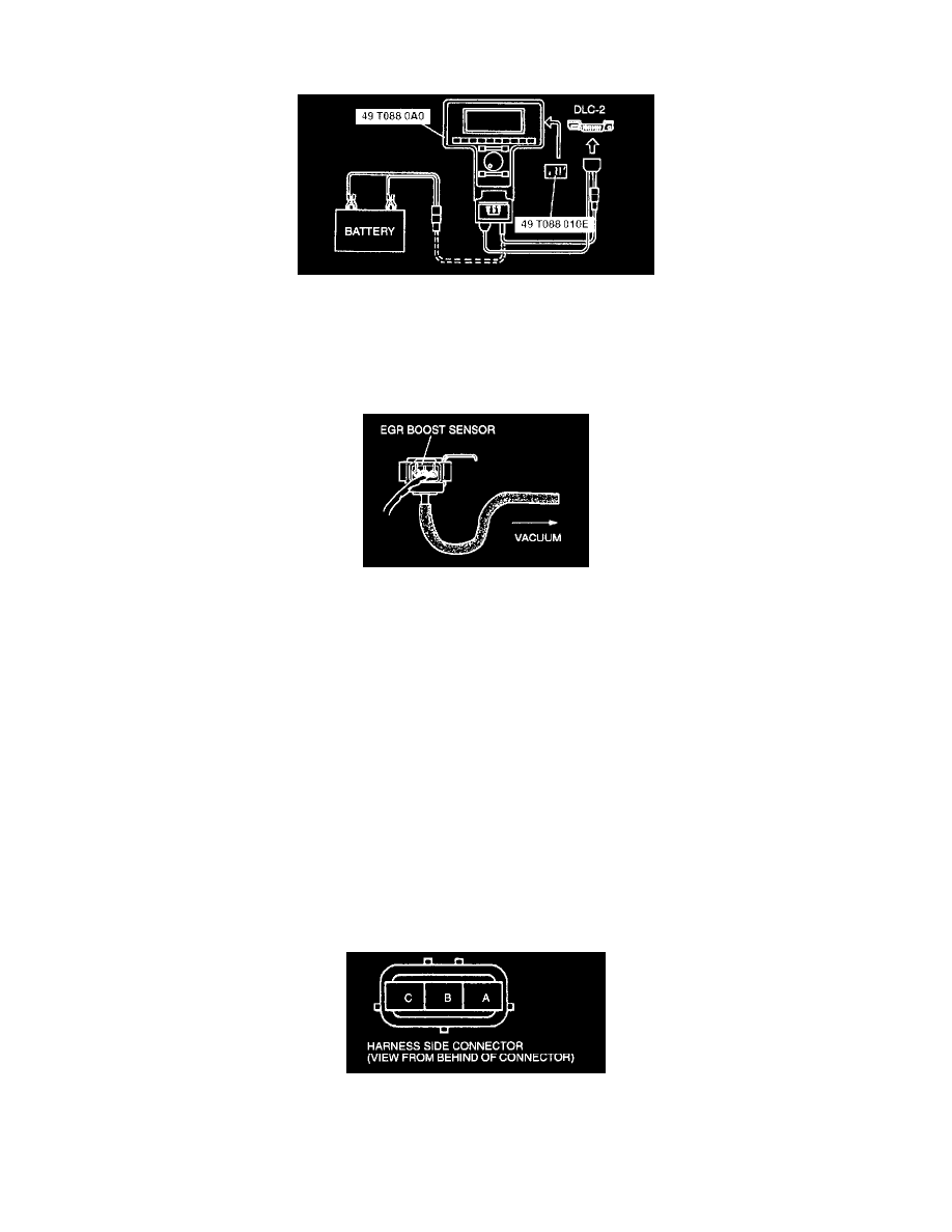
1. Connect the SSTs (NGS tester) to data link connector-2.
2. Select the "PID/DATA MONITOR AND RECORD" function on the NGS tester display.
3. Select "BARO V" on the NGS tester display and press START. The NGS measures and shows the voltage.
4. Turn the ignition switch to ON.
CAUTION:Do not apply a vacuum or pressure outside of the specified limits. Doing so will damage the EGR boost sensor.
5. Disconnect the vacuum hose between the EGR boost sensor and intake manifold.
6. Verity that the voltage at BARO V is as specified.
Measuring condition:
-
Input voltage 4.5 - 5.5 V
-
Outside temperature 10 - 50°C (50 - 122°F)
-
Sea level -200 - 3,000 m (-656 - 9840 ft)
Specification: BARO V: 2.5 - 4.9 V
7. Then apply the vacuum of -26.6 kPa (-200 mmHg, -7.85 inHg) to EGR boost sensor and verify that BARO V from step 6 is changes within
specified.
Specification: BARO V variation: 1.0 - 1.3 V
8. If not as specified, perform the following inspection.
(1) Harness continuity
-
Between PCM terminal 30 and EGR boost sensor terminal A
-
Between PCM terminal 3H and EGR boost sensor terminal B
-
Between PCM terminal 31 and EGR boost sensor terminal C
(2) Terminal voltage
-
EGR boost sensor terminal A voltage: Below 1.0 V (Constant)
-
EGR boost sensor terminal C voltage: approximately 5.0 V (Ignition switch is at ON)
9. If terminal voltage is correct and there is harness continuity, replace the EGR boost sensor.